The general format of the Transaction Layer Package (TLP) is shown in the following figure:
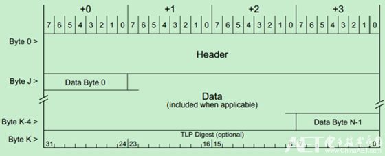
The previous article introduced that the TLP Header is 3DW or 4DW, the Data Payload is 1-12424DW, and the last TLP Digest (ECRC) is optional, which is 1DW.
The position of the TLP Header in the entire TLP is shown in the following figure. Note that the format and content of the TLP Header will change with the type of the TLP and the routing method.
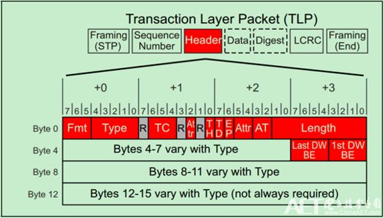
The type of TLP and the routing method are determined by Fmt and Type. This has been introduced in detail in the previous article on TLP routing. The figure above shows the same parts of the TLP Headers in various formats.
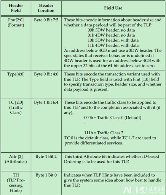
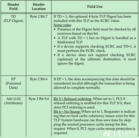
The role and meaning of each field is shown in the following table:
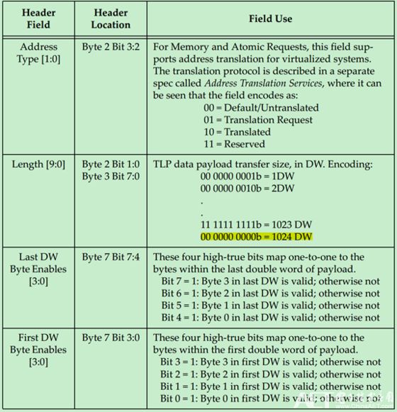
The Byte Enable is described in detail below. The unit of Data Payload in PCIe is DW, which means that the data size (address) needs to be DW aligned. However, in many cases, the size of the data is not an integer multiple of DW, so PCIe introduced Byte Enable to solve this problem. Use Byte Enable need to follow the principle:
• Byte Enable is active high and low (0) indicates that the corresponding Byte of the Data Payload will be considered invalid, ie it will not be used by the Completer.
· If the valid data is less than 1DW, Last DW Byte Enable should all be 0.
· If Data Payload is greater than 1DW, at least one bit of First DW Byte Enable is valid.
• If Data Payload is greater than or equal to 3DW, the valid bits in First DW Byte Enable and Last DW Byte Enable must be contiguous. In this case, Byte Enable can only be used to adjust the start address and end address.
• If Data Payload is equal to 1DW, the valid bits in First DW Byte Enable may be discontinuous.
· If Data Payload is equal to 2DW, the valid bits in First DW Byte Enable and Last DW Byte Enable can be discontinuous.
The DW in the write request is equal to 1, but none of the First DW Byte Enable is valid, but it is allowed, but such a request has no effect on the Completer.
If the read request DW is equal to 1, but none of the First DW Byte Enable is valid, then the Completer will return a 1DW Data Payload, but the data is invalid. This method is often used for Flush Mechanism.
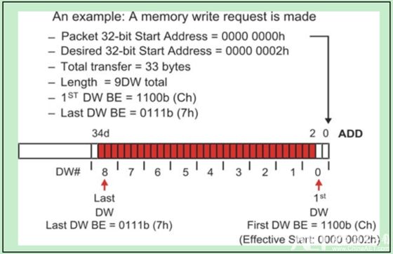
A simple Byte Enable example, as shown below:
Data Payload on TLP is:
· The size of the Data Payload is determined by the Length in the TLP Header.
· Data Payload uses Little Endian, which means that the low byte is stored in the lower address.
• The size of the Data Payload is not the size of valid data. The size of the valid data is determined by Data Payload and Byte Enable.
• When the TLP type is Message, Length is generally reserved unless the Message is with data (MsgD).
• The size of the TLP's Data Payload must not exceed the value of Max_Payload_Size, which is located in the Device Control Register. For a large amount of data, it can only be sent multiple times. For read requests, there is no Data Payload, which means that the rule does not apply to read requests.
· It is important to note that there is no way to cross a 4KB address boundary between the start address and the end address.
Cable Management,cable organizer,wire management,cable cover wall
NINGBO UONICORE ELECTRONICS CO., LTD , https://www.uniconmelectronics.com