Micropower DC-DC power modules are widely used in circuit design due to their high integration, high reliability, and simplified design. Although its application circuit is simple and easy to operate, it often encounters some common problems when it is applied. For this article, a detailed analysis of the common application problems of power modules and how to troubleshoot them.
Micro-power DC-DC power modules are favored by many electronic designers because of their high integration, high reliability, and simplified design. Although the power module is simple in operation and simple in operation, it often encounters some common problems when it is applied. For this article, the common application problems of power modules and how to troubleshoot them are analyzed in detail, and it is hoped that it will help the designer's power module selection.
Frequently Asked Questions 1: Output ripple noise is too largeCause 1: When the module is in use, the load is a dynamic load, so that the peak-to-peak value of the module output voltage becomes larger, but note that this is not ripple noise.
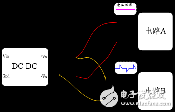
When the load current is periodically abruptly changed, the peak-to-peak value of the module output voltage becomes large. This is a transient amount, but it is sometimes mistaken for ripple noise. Therefore, when using a power module to supply power to multiple circuit units, for circuits with periodic load changes, the front stage needs to increase π-type filtering to reduce the interference of transient changes of this part of the circuit to other circuits.
For example, in the following figure, the circuit B fluctuates due to a change in the magnitude of the load. In order to reduce the interference of circuit B to circuit A, it is recommended to add π-type filtering at the input of circuit B.

Figure 1 circuit link block diagram
Cause 2: Oscilloscope ground problem
When testing the ripple noise of the power supply output, the ground clamp of the oscilloscope forms a loop with the ground and module output pins. Similar to the antenna receiver, it introduces other noise. If the environmental interference of the test is large, this noise will also be introduced by the oscilloscope, affecting the results of the ripple noise test.
And the ground of the oscilloscope probe we usually buy is connected to the ground wire inside the oscilloscope. This kind of situation has weak anti-interference ability to power frequency interference, and it is easy to introduce interference noise. Therefore, it is best to ensure that the oscilloscope probe is floating (using the oscilloscope's power ground or directly using a battery-powered oscilloscope) to reduce the introduced interference. If the power supply of the measurement object is also floating, it is better, so that the circuit characteristics are not changed, and the module output noise is increased.
Problem 2: The output voltage is low after the module is started.Reason 1: The input has an anti-reverse circuit

Figure 2 Block diagram of anti-reverse link
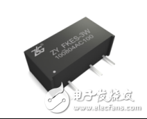
Example: The ZY_FKES-3W module in Figure 2 is a constant voltage input unregulated output module whose output voltage varies with input voltage and load size. Since the anti-reverse diode is added to the input side during circuit design, this causes the voltage at the input of the module to decrease and the output voltage to become smaller. Because we are designing the use of anti-reverse diodes, consider the forward voltage drop of the diode.
Cause 2: The output lead impedance is too large or the voltmeter connection is not standardized.

Figure 3 module connection block diagram
When using the power module, we are testing the output voltage, often trying to directly test the voltage at the input of the power supply circuit. However, since the impedance between the output of the module and the input of the power supply circuit is too large, the measured value is lower than the actual value. Therefore, when testing the output voltage of the power module, the voltage between the module's output pins should be measured instead of the voltage at the input of the power supply circuit.
Cause 3: When using the module, the required power module power is not accurately estimated, so that the module is overloaded or overloaded.

For example, the ZY_FKES-3W constant-voltage input unregulated output power module has a rated power of 3W, that is, the power range used by the module cannot exceed 3W. When the ZY0505FKES-3W module outputs 400mA at 5V input, the output voltage is about 4.98V. When the output is 600mA, the output voltage is about 4.88V. If it is overloaded, the output voltage will be lower. As the load increases, the output voltage is reduced, and this constant voltage input is characteristic of the unregulated output module.
Choose high-quality isolated power modules to make circuit design more efficientThe isolated power supply module independently developed and produced by Zhiyuan Electronics has a wide input voltage range and is isolated from 1000VDC, 1500VDC and 3000VDC series. It has various package types and is compatible with international standard SIP, DIP and other packages. It can also be provided according to the special conditions of the project. Customized tailor-made, custom-designed features, specially packaged isolated power supply.

Zhiyuan electronic power module is widely used in power supply and industrial automation because of its high efficiency, wide input voltage range, small size, high reliability, good impact resistance, good isolation and wide temperature range. , communications, medical, transportation, building automation, instrumentation and automotive electronics.
Shenzhen Jianjiantong Technology Co., Ltd. , https://www.mct-sz.com