Abstract : The rapid development of information technology has changed people's home concept. Establishing an efficient and low-cost smart home environment has become the focus of attention. Using the graphical software LabVIEW 2012 as the development platform, the NI USB-6009 data acquisition card, SIM300 GSM module and USB camera were selected to design a smart home monitoring system. The system realizes real-time monitoring of environmental parameters such as home indoor temperature, humidity, illuminance, gas smoke and security status and remote GSM short message alarm. The system is reliable in operation, friendly in human-machine interface, easy to operate, scalable, and tested. low cost.
This article refers to the address: http://
With the rapid development of measurement and control technology and network communication technology and the change and improvement of people's home concept, modern society family members have made the ideal goal of pursuing the multi-information security, comfortable and convenient living environment brought by digital home intelligence. Therefore, how to build a smart home system with high efficiency, low cost and easy expansion has become the focus of attention. Virtual instrument emphasizes the new concept of "software is instrument". It is a computer with computer-based hardware platform, corresponding test function hardware as I/O interface, using instrument software to define and design test function by users. Instrument system, virtual instrument has three basic functions: data acquisition, data analysis and processing, and result output display. LabVIEW is the virtual instrument software development platform of NI National Instruments. It is the most complete and widely used graphical software development integration environment. LabVIEW has a rich toolkit with high programming efficiency and greatly shortens system development time. Based on the current monitoring requirements of smart homes, this design uses virtual instrument technology, using LabVIEW2012 as the software platform, using NI's USB-6009 data acquisition card, SIMC OM's SIM300GSM module and USB camera to build a home environment monitoring and home. Intelligent home monitoring system with integrated functions such as electrical control, security alarm and video surveillance.
1 overall design of the system
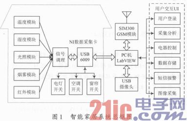
The overall block diagram of the system is shown in Figure 1. The system collects information such as temperature, humidity, illuminance, gas leakage, and perimeter security status of the home environment through various sensor modules. After signal conditioning, it is loaded into the LabVIEW via USB-6009 data acquisition card. The monitoring platform completes the display, analysis, storage and alarm functions of environmental parameters, and completes the automatic control of lighting, air conditioning, curtains and other household equipment according to the corresponding parameters. The video probe is connected to the PC through a USB port, and collects image and video of the home environment in real time to realize video monitoring. The SIM300 GSM module exchanges data with the LabVIEW platform through the VISA serial port. When an abnormal alarm occurs in the system, the system automatically sends an SMS mobile phone SMS alarm to the user to realize the remote alarm function.
2 system hardware part design
2.1 USB-6009 data acquisition card
The way LabVIEW software obtains data is done by driving the I/O interface device. The I/O interface device used in this system is USB-6009 of NI Company of USA. It is a USB bus-powered 14-bit multi-function DAQ data acquisition module. The module provides 8 analog input channels, 2 analog output channels, 48 ​​kS/s single channel sampling rate, 12 digital I/O lines, 32-bit counters, and is compatible with LabVIEW. The USB6009's plug-and-play installation minimizes configuration and setup time. The USB bus power supply eliminates the need for external power supplies and is easy to use.
2.2 Sensor module
The sensor module is composed of temperature and humidity sensor CHT3W2TLD, illuminance sensor, smoke sensor MQ-2, infrared sensor E18-D50NK and so on. Honeywell's temperature and humidity sensor can simultaneously collect temperature and humidity, and has good linearity. The output voltage range is 0~5 V, temperature measurement range: -20~85°C, accuracy: ±0.5°C, humidity measurement range: 0~ 100% RH, accuracy: ± 5% RH. The illuminance is detected by a photoresistor. The indoor smoke and gas leakage are monitored by MQ-2 smoke sensor. The working voltage is DC 5 V, analog and TTL level dual signal output, and the effective signal is low when TTL output. The sensor is low in cost, good in sensitivity, reliable in stability, and has fast response recovery characteristics. Infrared sensor E18-D50 NK detection distance can be adjusted according to requirements, with long detection distance, low visible light interference, low price, easy assembly, easy to use, etc. The working voltage is DC 5 V, and the output is TTL level signal.
2.3 SIM300 GSM SMS Module
GSM (Global System for Mobile Communication) network is a communication network system based on time division multiple access technology and frequency division multiple access technology. It has wide network coverage, high security and confidentiality, and does not need to set up a dedicated network and maintain the network. It has the advantages of fast transmission speed and low cost, and has been widely used in remote intelligent monitoring systems. The SMS alarm function of this system adopts SIMCOM GSM module of SIMCOM to send SMS SMS. The SIM300 is a low-power module supporting GSM/GPRS 900/1 800/1 900 MHz tri-band. It has a built-in processor and supports a standard RS 232 interface for easy connection to a PC. In this system, the communication between LabVIEW and SIM300 module is realized through RS 232 interface, and the SMS control program is developed by LabVIEW software to realize the remote SMS alarm function of the mobile phone to the smart home system.
3 system software program design
3.1 System User Interface Design
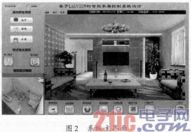
After the user successfully logs in to the system, you can enter the main interface of the smart home system, as shown in Figure 2. In the main interface, the user can monitor the temperature, humidity, illuminance, flammable gas, home security and other information in the living room, bedroom and kitchen, and analyze and judge the collected signals. When there is gas leakage and smoke. When someone is in an abnormal situation, the system issues a high-brightness alarm, alarm information storage, and remote mobile phone SMS alarm.
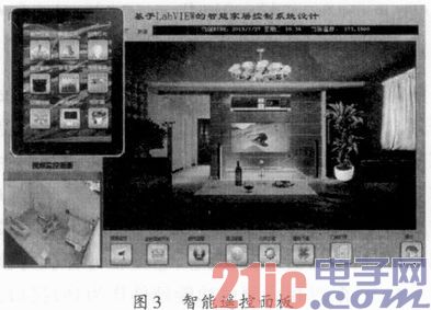
The system is set to two modes: one person and no one. When the system is in the human mode, only the real-time monitoring of the home environment is realized. When the system is set to the unmanned mode, the system alarm processing function is turned on. In addition, the system considers the design of the intelligent remote control panel. As shown in Figure 3, by clicking each function button in the remote control panel, the software and hardware control of the lights, curtains and air conditioners in each room can be realized.
3.2 Data Acquisition Procedure
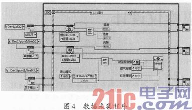
The main program adopts the producer-consumer (event) architecture. The producer loop is mainly responsible for the multi-channel data acquisition and analysis display of the system and the response of the user interface events. The consumer cycle completes the video monitoring and alarm program according to the producer's queue information. Processing. With this architecture, programs can respond to events faster and execute more efficiently. As shown in FIG. 4, the data collection and data display refreshing is performed every 200 ms in the producer loop by using the timeout branch setting of the event structure to ensure the real-time performance of the display interface. The NI DAQmx function is used in the program to collect, display and threshold the parameters of the home environment. The specific method based on NI DAQmx data acquisition is: firstly create DAQmx data channel according to the acquisition task, set data acquisition parameters, then call DAQmx read or write function to realize signal acquisition and control, and finally stop DAQmx task.
3.3 System Alarm Handler
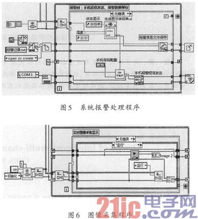
When an alarm occurs in the system, LabVIEW will use VISA to communicate with the serial port of the GSM SMS module. VISA (Virtual Instrument Software Architecture) is an advanced application programming interface developed by National Instruments to communicate with various instrument buses. By calling the off-the-shelf VISA node function in LabVIEW, users can easily build a data acquisition and measurement and control platform based on existing serial hardware devices without adding other new hardware devices. In addition, the VISA function not only communicates with the serial port, but also with various buses such as GPIB, USB, PXI, VXI and Ethernet, thus making the serial port program written in VISA with the VISA node function very portable. When the hardware interface changes, only the appropriate parameter configuration modification of the VISA function can complete the development, transplantation and upgrade of different platforms and different types of devices, thereby greatly improving the development efficiency. As shown in Figure 5, three VISA serial operation nodes in LabVIEW are invoked, which are configured with serial port nodes, VISA write nodes, and VISA shutdown nodes. The program first sets the baud rate, verification mode, data bit stop bit and other parameters of the serial communication. Then call the VISA write function, and send the alarm information to be sent to the SIM300 GSM module through the AT command, thereby realizing the remote transmission of the mobile phone short message. After the entire program is finished running, use VISA to close the node and release the occupied serial port resources. In addition to the SMS alarm, the system will automatically store the information in the alarm situation, and save the time and data information of the alarm in the alarm record.txt file in the main program path for the user to query.
3.4 Image Acquisition Program
In order to reduce the cost and facilitate the installation of the system, the currently popular USB camera is used in conjunction with NI's IMAQ Vision module for visual image acquisition. The system first installs the same NI Vision Development Module visual development module as the LabVIEW version, and then installs the NI-IMAQ for USB Cameras-USB camera driver. With this driver, all DirectShow image acquisition devices can capture images in LabVIEW. . Figure 6 is a block diagram of the image acquisition program. In the producer-consumer architecture, the operation instructions of the video monitoring are transmitted in a queue. When the interface event of the monitoring switch is pressed, the command is run into the queue in the producer loop, in the consumer cycle. Turn on the camera after receiving the run command to avoid unnecessary waste of resources.
4 Conclusion
The system uses virtual instrument technology, measurement and control technology and GSM network communication technology to realize a smart home monitoring system and remote alarm based on LabVIEW. The LabVIEW EW software is selected for the system monitoring interface, which reduces system development time and improves design efficiency. The actual operation shows that the system is stable and reliable, the human-computer interaction interface is friendly, the cost is low and the efficiency is high, and it is easy to expand and maintain. The system can be applied not only to homes, but also to security monitoring and remote control in warehouses, factories and greenhouses, and has a broad market application prospect.

A solar cell panel, solar electric panel, photo-voltaic (PV) module, PV panel or solar panel is an assembly of photovoltaic solar cells mounted in a (usually rectangular) frame, and a neatly organised collection of PV panels is called a photovoltaic system or solar array. Solar panels capture sunlight as a source of radiant energy, which is converted into electric energy in the form of direct current (DC) electricity. Arrays of a photovoltaic system can be used to generate solar electricity that supplies electrical equipment directly, or feeds power back into an alternate current (AC) grid via an inverter system.
Solar Panel,200w Folding Solar Panel,Folding Solar Portable Power Station,Sunpower Solar Cell
suzhou whaylan new energy technology co., ltd , https://www.nbwhaylan.com