introduction
All electronic products must be tested for EMI / EMC before going to market to prove that they will not cause interference or be interfered by other equipment. For testing purposes, these products can be divided into two categories: active radiation products and non-active radiation products, for example, cell phones and walkie-talkies that actively radiate energy, while TVs, computers, and laptops should not radiate energy.
Different types of products and test institutions, EMI / EMC test requirements are also different. However, EMI / EMC testing can be roughly divided into two categories:
Radiation: This test limits the amplitude and frequency of the signal radiated or conducted by a product so that it will not interfere with other products.
Sensitivity (also called immunity): This test shows the product's ability to suppress radiation by limiting the amplitude and frequency of radiated and conducted signals that can interfere with the device's normal operation.
As mentioned above, EMI can be divided into conducted interference and radiated interference. Since all EMI radiation is generated by current, these two types of interference are related to each other. But not all currents will produce radiation. Therefore, we must first analyze and suppress the problem of radiated interference, and then deal with the problem of conducted interference. For these two types of interference, radiated interference is more difficult to predict and suppress. Therefore, it is the main reason for failure of EMI test of most non-active radiation products. Here, we will focus on how to solve the radiated interference problem of the audio / video interface that is common in many products.
Various methods can be used to meet the conditions defined in the EMI / EMC regulations. But most of these methods can be classified into two categories: shielding and filtering. In actual products, these methods must be combined with specific applications to achieve a comprehensive EMI solution. For example, in most products, a metal shell is used to shield the radiation, and LC or RC filters are used to reduce the conducted interference of the input / output lines. In addition, a dithered clock can also be used to extend the spectral range to reduce the filtering or shielding requirements of specific applications.
When the EMI performance of the product basically meets the requirements, it will be taken to a certified laboratory for formal testing. If the product passes the test, it can be put on the market; if it fails, it means there is a problem. When solving problems, even a small change can take a long time. This may delay the time to market of products, because both the international and domestic markets require products to pass EMI / EMC compatibility tests1. As a result, EMI design often sacrifices the video performance of the product to ensure that it passes the test. In modern design, the physical size and cost of the components required to pass the EMI test need to be considered, so the video performance will be sacrificed.
The size of modern audio / video analog interfaces continues to decrease, but the performance expectations are very high, which poses a very serious challenge to the design. To solve this problem, first find out the source of most EMI / EMC test failures; and then explore feasible solutions.
Source of test failure
EMI / EMC test failure usually occurs at the weakest link in product design—signals (and interference) enter or leave the shielded and filtered mechanism from this link. Among the audio / video interfaces, the weakest point is the cable connecting the devices. They are equivalent to antennas. For computers, the cable connecting the display and speakers to the PC is the weakest link, and it often causes EMI / EMC problems. We may think that only high-bandwidth video interfaces will cause this problem, while low-frequency audio interfaces will not have this problem. This is true when all amplifiers use Class A audio amplifiers. However, the currently used high-efficiency class D amplifiers 2 all have high-frequency switching signals, and if there is no proper filtering and shielding, there will also be EMI problems.
In the past, large external filters and / or shielded cables could be used to solve these problems. But these methods not only increase the cost, but also affect product performance and increase product size. As these products continue to shrink in size and evolve into current audio / video players, EMI / EMC solutions must reduce product size while maintaining or even improving system performance. To achieve this goal, small devices such as the MAX9511 graphic video interface and the MAX9705 Class D audio amplifier have been developed, which can provide excellent EMI performance. In order to show how this improvement is achieved, one can examine the audio and display interface 3 of a common PC and the EMI performance provided by these tiny devices. First, we should understand the various EMI problems that must be solved in the audio / video interface design, and then give a solution to these problems.
Video and EMI
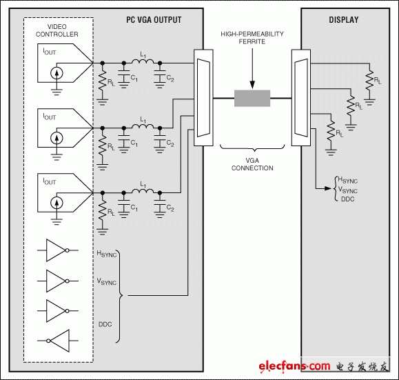
The video format commonly used by computers, which we call "graphics", is not the same as the video format of television4. Computer video has red, green, and blue (R, G, B) analog video signals, as well as logic signals including line, field sync, and DDC5, all of which have fast rise / fall times. The video connector usually uses a high-density ultra-micro D-type connector to connect the monitor and the PC (Figure 1). Although this solution combines measures such as video signal shielding (coaxial) and common-mode choke (CMC) to reduce radiated and conducted EMI, it still needs to increase filtering to ensure EMI requirements are met. In broadcast video applications, similar filtering measures are used to eliminate aliasing defects in TV images. However, this cannot be done in graphics video because the purpose of graphics video is to reproduce a checkerboard pattern of "on" and "off" pixels at the highest possible resolution. Therefore, in order to achieve the best display performance, we hope that the larger the bandwidth, the better. However, in practical applications, EMI and video performance must be weighed, so video bandwidth has to be sacrificed. For multi-signal video interfaces, multiple factors need to be weighed.

Figure 1. Typical VGA connection and video signal generating radiated EMI
For example, when filtering a video signal, there will be a time delay, and if the delay time of each video channel (R, G, and B) cannot be precisely matched, a color edge effect will occur. In order to avoid this phenomenon, the group delay and group delay matching of the video channel must be precisely controlled6. RGB video is extremely susceptible to these parameters7. For best performance, the group delay must be consistent with the frequency, and the minimum group delay match between channels must be kept within ± 0.5 pixel time. If the matching can be so precise, then the synchronization signal must also track the channel delay to correctly display the image frame. After this is done, the multi-video resolution problem supported by the PC needs to be resolved.
In this application, it is very difficult to achieve the best performance with a fixed frequency filter. If we design a filter to suppress EMI at the lowest resolution, the filter's stopband will intervene in the signal bandwidth of the higher resolution format, thereby affecting the higher resolution video performance. If the filter is designed for the highest resolution format, it may not meet EMI requirements. Obviously, the best solution is to use a "tunable" filter whose frequency response can track the display resolution, but this method will increase the cost and may also increase the product size. In addition, the impact of synchronous and fast rise / fall times of DDC drivers on EMI performance is also important. Therefore, in any complete EMI solution, methods that can delay these rise / fall times must be included. There are still some historical issues, such as the video DAC load detection function to meet the plug and play requirements.
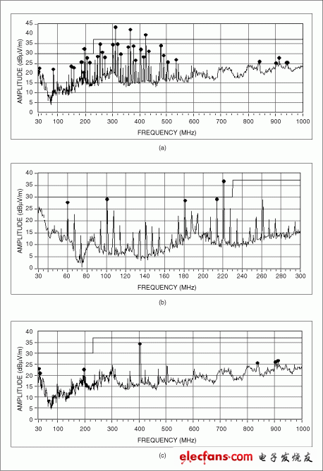
MAX95118 can realize all these functions. As shown in Figure 2, the high-resolution graphics card output using MAX9511, using LC filter scheme, and the EMI characteristics of the original output without filtering.

Figure 2. EMI radiated under three conditions: a) without filtering, b) using passive LC filter, c) using MAX9511
CT For Three-phase Electricity Meters
Our company`s current transformers have high precision,wide range,small volume and good linearity that can be used to the field of electronic watt-hour meter, electric energy metering, electronic detection.
Performance
â—Power frequency insulation strength:The insulation between the primary winding and the secondary winding and the ground part of the CT can bear 4kV power frequency voltage for 1minute
â—Interturn insulation strength:The secondary open circuit, the primary winding through the rated current 1min, no inter-turn damage in the transformer
â—The deviation is better than the industry standards and national standards
Three-Phase Electricity Meters Ct,Dc Resistance Current Transformer,Best Ct For Dc Resistance,New Design Ct
Anyang Kayo Amorphous Technology Co.,Ltd. , https://www.kayoamotech.com