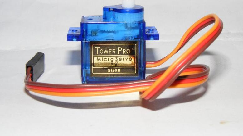
The steering gear first appeared in the movement of aeromodelling. In the aviation model, the flight attitude of the aircraft is achieved by adjusting the engine and each control rudder. For a simple four-way airplane, there are several places on the plane that need to be controlled:
1. The amount of engine air intake to control the engine's pull (or thrust);
2. Aileron rudder (installed on the trailing edge of the aircraft wing) to control the roll motion of the aircraft;
3. Horizontal rudder surface, used to control the aircraft's pitch angle;
4. Vertical rudder surface, used to control the yaw angle of the aircraft;
The remote control has four channels, corresponding to four servos respectively, and the steering gear drives the rotation of the rudder surface through a connecting rod and other transmission elements, thereby changing the movement state of the aircraft. The servo is thus named: Servomotors that control the rudder.
Not only in the model aircraft, but also in other model movements can see its application: used to control the rudder on the ship model, used to turn the car model and so on. It can be seen that the servo can be used to achieve any operational action.
How does the servo work?In general, the steering gear mainly consists of the following parts: rudder plate, reduction gear set, position feedback potentiometer 5k, DC motor, control circuit board, etc.
Working principle: The control circuit board receives the control signal from the signal line (the specific signal will be talked about again), and controls the rotation of the motor. The motor drives a series of gear sets, and after deceleration, it is transmitted to the output rudder plate. The output shaft of the servo and the position feedback potentiometer are connected. When the rudder plate rotates, it drives the position feedback potentiometer. The potentiometer will output a voltage signal to the control circuit board for feedback, and then the control circuit board determines the motor according to the position. The direction of rotation and speed, so as to achieve the target stop.
The basic structure of the steering gear is like this, but there are many kinds of implementation. For example, there are brush and brushless motors, gears are divided into plastic and metal, the output shaft has sliding and rolling points, the shell has plastic and aluminum alloy, the speed is divided into fast and slow speed, volume Big, medium, small, and so on, the combination is different, and the prices vary. For example, in which the small steering gear is generally called a micro-rudder, the same kind of material is more than double the medium-sized condition, and the metal gear is more than double the plastic gear. Need to use different types as needed.

1. Definition of PWM signal
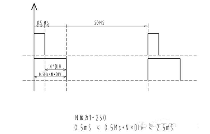
The PWM signal is a pulse width modulated signal characterized by the time width between its rising and falling edges. The specific time width agreement refers to the following description. The servos we currently use mainly depend on standard protocols of the model industry. With the gradual independence of the robotics industry, some manufacturers have introduced new servo protocol. These servos can only be applied to the robotics industry and cannot be applied to the traditional ones. The model above. At present, the steering gear may be the product of this transitional period. It adopts the traditional PWM protocol and its advantages and disadvantages are clear at a glance. The advantages are industrialization, low cost, large rotation angle (the current production can reach 185 degrees); the disadvantage is that the control is more complex, after all, using the PWM format. However, it is a digital servo with low requirements for PWM signals: (1) It does not need to receive instructions at any time to reduce the CPU fatigue; (2) It can position self-locking, position tracking, which is beyond the ordinary Stepper motor.

The following points are noted in the PWM format: (1) The rising edge is at least 0.5mS, which is between 0.5mS and 2.5mS. (2) The timing of the falling edge of the HG14-M digital servo is not required. Currently, 0.5Ms is used. That is to say the PWM waveform can be a standard square wave with a period of 1mS; (3) HG0680 is a plastic gear analog servo, which requires continuous supply of PWM signal; it can also input a standard square wave with a period of 1mS. The follow-up performance is very good and very close.
2. PWM signal control accuracy
If you use an 8-bit microcontroller AT89C52CPU, the data resolution is 256, then after the servo limit parameter experiment, it should be divided into 250 copies. Then the width of 0.5mS---2.5Ms is 2mS=2000uS. 2000uS÷250=8uS, then: The PWM control accuracy is 8us. We can incrementally control the servo's rotation and positioning in units of 8uS. The servo can rotate 185 degrees, then 185 degrees ÷ 250 = 0.74 degrees, then: the servo control accuracy is 0.74 degrees.

1DIV=8us; 250DIV=2ms The value in the time base register is: (#01H)01----(#0FAH)250. A total of 185 degrees, divided into 250 locations, each location called 1DIV. Then: 185÷250=0.74 degrees/DIVPWM rising edge function: 0.5ms+N&TImes;DIV0us≤N&TImes;DIV≤2ms0.5ms≤0.5ms+N&TImes;DIV≤2.5ms
SCM control steering gear and programThe servo control signal is a pulse width modulation signal, so it is convenient to interface with the digital system. As long as the standard digital control equipment can generate control signals can be used to control the steering gear, such as PLC, microcontroller and so on. This article describes the use of 51 series single-chip microcontroller servo control signal generated by the method of programming language is C51. The reason why this method was introduced is because the author used 2051 to achieve, in a responsible attitude, so dare to write here. The program used my four-legged walking robot and was modified. SCM is not the best way to control the steering gear, I hope to play a role in this.
The 2051 has two 16-bit internal counters. We use it to generate a 20-ms pulse, and change the output pulse width as needed. The basic idea is as follows (please check the following program):
I use the crystal frequency is 12M, 2051 clock cycle is 12 crystal period, exactly 1/1000ms, the counter counts every 1/1000ms. Take the counter 1 as an example, first set the initial value of the pulse width. The initial value in the program is 1.5ms. You can change it by changing the value of a at any time in the for loop. Then set the initial value of the counter to a, and set the output p12 to High position. When the count is over, the trigger counter overflow interrupt function is void TImer0 (void) interrupt1using1. In the subroutine, change the output p12 to invert (in this case, jump to low) and use 20,000 (representing the 20ms period) to subtract the high bits. The time a, which is the lower time in this cycle, c=20000-a, and set the initial value of the counter at this time to c, until the timer generates an overflow interrupt again, and repeats the previous process.
#include"reg51.h"
#defineucharunsignedchar
#defineuintunsignedint
Uinta,b,c,d;
Sbitp12=P1^2;
Sbitp13=p1^3;
Sbitp37=P3^7;
Voidtimer0(void)interrupt1using1
{p12=! P12;
c=20000-c;
TH0=-(c/256); TL0=-(c%256);
If(c)=500&&c=2500c=a;
Elsec=20000-a;
}
Voidtimer1(void)interrupt3using1
{p13=! P13;
d=20000-d;
TH1=-(d/256); TL1=-(d%256);
If(d)=500&&d=2500)d=b;
Elsed=20000-b;
}
Voidmain(void)
{TMOD=0x11;
P12=1;
P13=1;
a=1500;
b=1500;
c=a;d=b;
TH0=-(a/256); TL0=-(a%256);
TH1=-(b/256); TL1=-(b%256);
EA=1;
ET0=1; TR0=1; EX0=1; EX1=1;
ET1=1;TR1=1;
PX0=0; PX1=0; PT1=1; PT0=1;
For(;;)
{
}
}
Because the output of the pulse signal is handled by the overflow interrupt function of the timer, the time is very short, so it can be ignored in the occasion where the accuracy requirement is not high. So if you ignore the interrupt time, from another point of view is the main program and the pulse output is in parallel, so only need to change the value of a in your main program according to your requirements, for example, let a change from 500 to 2500, you can let The servo changes from 0 degrees to 180 degrees. Another thing to keep in mind is that the rotation of the servo takes time, so the value of a in the program cannot change too quickly, otherwise the servo will not keep up with the program. According to the needs, choose the appropriate time delay and use a increment cycle to make the servo rotate smoothly without generating the pulsation like the stepper motor. These also require concrete experience in practice.
The speed of the servo depends on the speed of change of the pulse width you give it. For example, when t=0, the pulse width is 0.5ms, and when t=1s, the pulse width is 1.0ms. Then, the steering gear will change from the position corresponding to 0.5ms to the position corresponding to 1.0ms. How is the rotation speed? What? In general, the maximum rotation speed of the 3003 is 0.23s/60 degrees at 4.8V, that is, if you request a speed faster than this, the steering engine will not respond; if you require a speed slower than this, you can Linearize the pulse width change to your desired time, make a loop, and increase the pulse width bit by bit to control the servo speed. Of course, exactly how much this point is, it needs to be tested. Otherwise, if it is not appropriate, the steering gear will hop to the stepper motor and try to change this “pointâ€. Your servo moves more smoothly. It is also important that the servo always has a process in which the speed is increased from zero to decelerated to zero each time the pulse width value changes. This is why the rudder machine moves like a stepper motor.
Touch Panel For Iphone X,Touch Screen With Oca,Touch Screen Without Ic,Touch Screen Panel With Flex
Shenzhen Xiangying touch photoelectric co., ltd. , https://www.starstp.com