Today, more and more electronic devices are being widely used in the automotive industry. Estimates show that today's electronic devices account for 30%-40% of the cost of a car. These electronic devices include not only functional devices such as engine control units, brake systems and transmission control devices, but also more consumer electronics such as entertainment and navigation systems. Recently, the use of LED technology in the automotive field has experienced explosive growth. For example, in Europe, all cars must have LED lights.
This article refers to the address: http://
Good thermal management is becoming more and more important when designing these electronic products, including LED systems. LEDs constantly emit heat, and the lampshade becomes smaller and smaller. Brightness (and power consumption) is increasing, but LEDs that are closely aligned (car front and rear lights) are not equipped with corresponding cooling fans. Therefore, reliability and performance are bound to be affected. If the LED exceeds the critical junction temperature, two problems will occur: the LED light will dim; if the temperature continues to be too high, the life of the LED light will be shortened and then prematurely scrapped. The average life of LED lights on cars is several thousand hours, and premature retirement will bring additional warranty costs to manufacturers.
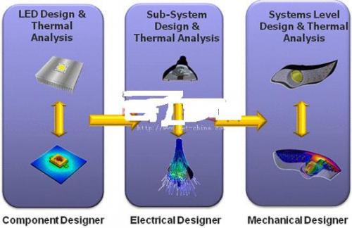
Excellent thermal management depends on good thermal design. As shown in Figure 1, the LED component is the first link in the design process. Component designers use thermal analysis software and test equipment to analyze the material and structure of the component to ensure that the heat generated by the junction can easily be dissipated through the LED component layer. The subsystem designer will arrange the LED components in an array, add heat sinks and other cooling devices, and then analyze the product again. They may adjust the separation distance between LED components or add additional cooling to ensure that the LEDs do not exceed the critical temperature. The final step is usually done by a mechanical design engineer using a mechanical computer aided design (MCAD) system, where the designer places the aligned LED lights into a lampshade (such as a car headlight) while utilizing advanced computational fluid dynamics (CFD). The software performs thermal analysis.

Figure 1: Thermal analysis of the various aspects of the LED design process is a necessary step for good thermal management.
It should be noted that solving the thermal management problem of the component does not mean that the thermal management problem of the subsystem is also solved. Solving the thermal management problem of the subsystem does not mean that the thermal management problem of the system is solved. Only by solving all these problems (see Figure 1) can we say that this is a good design.
Design blanks <br> So where is the problem? The industry has been using excellent CFD thermal analysis software for many years. Products such as FloTHERM are fast, accurate, and easy to use, and require no external experts to complete the analysis. The problem is that the accuracy of the software analysis results depends on the accuracy of the component model being entered. If the input component model is inaccurate, the software's results will only mislead the designer, no matter how perfect the analysis process.
But the key is that the typical LED data sheet provided by the supplier will only show its total power consumption (such as maximum forward current and voltage) and a single thermal resistance between the junction and some reference points (such as solder joints). There is no information on how heat passes through the layers in the package and dissipates it. There is also no description of the thermal path/obstacle that can be used to define the thermal resistance and heat capacity of each layer. What problems will arise in this way? Typically, thermal management experts estimate the internal structure of the package and create a thermal model to describe the thermal resistance and heat capacity of each layer and structure. As long as a few percentage points of deviation occurs in this model, the analysis will be inaccurate. And there is no way to verify or judge the quality of such a thermal model.
So fundamentally, there is still a gap in the design of the cooling system. Thermal analysis is absolutely essential in all aspects of product development (components, subsystems, and the entire system). However, good thermal analysis results are only possible if the component thermal model is good. Without knowing the internal structure of the packaged components, we cannot define or verify the accuracy of the model, and usually the component suppliers will not disclose intellectual property in this area.
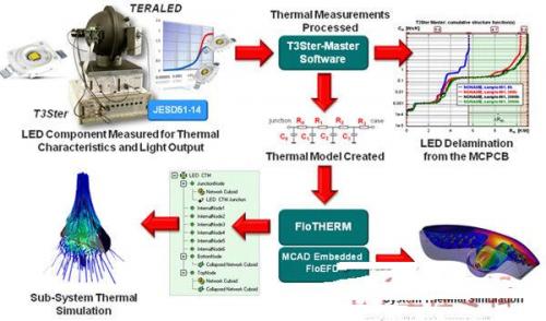
Filling in the gaps <br> The solution is to establish a bridge between hardware testing/measurement and thermal analysis by defining and verifying a simplified thermal model of the components shown in Figure 2. Existing hardware is capable of measuring the thermal characteristics of a component. With cutting-edge software, these measurements can be translated into simplified thermal and thermal capacity networks that we can read in thermal analysis software.
For example, Mentor's T3Ster hardware can be connected to the component under test to measure the transient temperature change of the junction, whether it is the heating process or the cooling process of the component, it can be accurate to 0.01 degrees Celsius. In the process of heat dissipation from the junction to the surrounding environment, more than 10,000 data points can be collected in one minute to describe the transient change of junction temperature, and the transient change characteristics of the junction temperature represent the layers of the component. Thermal resistance and heat capacity. With this data, the analysis software can automatically generate LED simplified thermal models. An accurate and effective model was born.

Figure 2: Hardware testing and measurements can be used to create or verify LED simplified thermal modes.
In this way, we effectively fill the gaps in the thermal management design process and create accurate and efficient component thermal models. This technology is used by many people in the electronics industry.
LED suppliers are designed to use this technology to measure thermal performance and optimize it before measuring and creating a thermal model for the customer. Subsystem and system developers can use it to verify the thermal model obtained from the supplier or create the model themselves without the supplier providing the model. The reliability of electronic equipment is small, and the design responsibility usually falls on OEMs. Quality assurance and recycling issues directly affect their profit and loss. They need 100% confirmation that their product design is ok.
Additional benefits of heat measurement
LED suppliers and original equipment manufacturers currently use this hardware technology in many areas. LED suppliers will use it in the two most common ways.
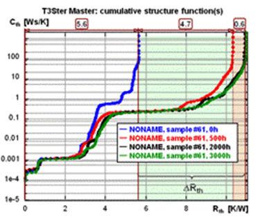
The first is lossless troubleshooting. In this case, the supplier can use thermal measurement technology to check the "internal" of the faulty part without having to separate this part. Figure 3 shows the corresponding example. The LEDs that have dropped in function after a few hours will be found out. In the thermal resistance-heat capacity diagram, the blue lines indicate the LEDs that have just been produced, and the other lines indicate LEDs that have been used for 500 hours, 2000 hours, and 3000 hours, respectively. Visible in the horizontal direction, there is a high thermal resistance layer on the line representing the used LED. This indicates a situation where material separation occurs at this location. The thermal conductivity of air is much smaller than the original material. This type of troubleshooting test can be used for LED and IC packages.

Figure 3: Thermal resistance - heat capacity curve The red, green and black lines in the horizontal direction represent the high thermal resistance layer and possible separation.
The second application is in the production process. In the production of LEDs, the parameters such as the thickness of the glue are not fixed, so this test instrument can be an important part of the production line. Sampling first, then quickly testing and comparing with standard devices, can quickly identify deviations in the production process and then correct them. The return on investment of this test equipment is very impressive. As a result, today's LED suppliers and original equipment manufacturers responsible for subsystem and system development can use a precise component to complete product design, application and failure analysis (Figure 4).

Figure 4: Complete thermal and optical measurement/calibration has now been applied to LED product design, production quality, and lossless failure analysis.
Support for the automotive supply chain
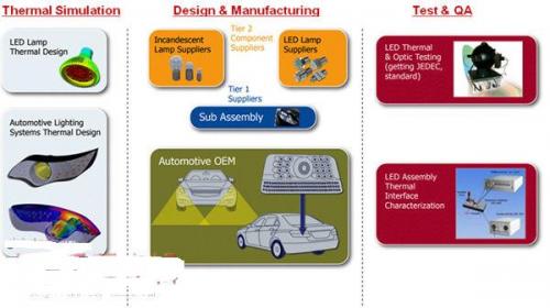
As shown in Figure 5, the supply chain for the automotive industry, we see that there are secondary and Tier 1 suppliers in the supply chain in addition to automotive OEMs. Good thermal design requires thermal analysis, and designers of both primary and secondary suppliers need to have this capability. This thermal analysis supports and validates the thermal measurements of components, subsystems, and systems through accurate and timely physical testing. Automotive OEMs will be able to demonstrate the high reliability and low energy performance of the products they purchase.

Figure 5: Thermal analysis and physical testing/calibration are required at all levels of the automotive supply chain.
As a result, while the use of fast “virtual samples†is widely used to make products faster and more competitive, the use of fast and accurate test and measurement tools for the supply chain is not to be underestimated. Otherwise, we will pay a high price when developing products with low reliability margins.
Label/Webbing Cutting Machine,Angle Cutting Machine,Textile Laser Cutter,Material Cutting Table
Kunshan Bolun Automation Equipment Co., Ltd , https://www.bolunmachinery.com