The method of designing a miniature electronic organ with a single chip microcomputer is introduced. The circuit, block diagram and program are given.
Keywords: single chip microcomputer, electronic keyboard, program
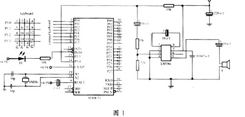
The single chip microcomputer is widely used because of its small size, strong function and low price. This article introduces the method of designing the micro-electronic keyboard with AT89C51 single-chip microcomputer. It only needs AT89C51 minimum system, expands a set of small keyboards (here, 4×4 keyboard is used as an example, it can be expanded as needed), and then add a piece of LM386 to make audio small power amplifier, output to the speaker. . The power supply can be supplied by three 5th batteries.
1 Design principle The tone is actually a signal with a fixed period. We can use the AT89C51's timer (such as T1) to control, output the square wave periodic signal on the P3.4 pin, and generate the tone. According to different buttons, adjust the overflow time of T1, and output the music of different frequencies, thus making a miniature keyboard.
The pitch (frequency) of each tone is fixed. Table 1 lists the sound name, frequency and the initial value of the timer T1 (8 MHz) for a total of 16 sounds. .
This article refers to the address: http://

2 hardware circuit design The electronic schematic of the micro-electronic keyboard is shown in Figure 1. The keyboard can be arranged into a piano keyboard with small buttons (they can be divided into several rows when the keys are too many), and a button indicator (D1) is added to the figure.
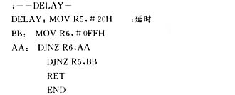
3 software design software consists of initialization program, main program, timer 1 interrupt service program, keyboard scan program and delay program.
(1) The initialization procedure is as follows: 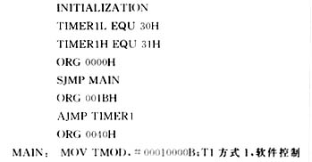
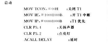
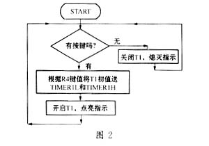
The main block diagram is shown in Figure 2.
(2) Main program: 
CJNE R4, #00H,
PLAYKEY; judges whether there is a key to press CLR TR1; no key presses to close T1
SETBP3.2; no key presses the off indicator SJMPSTART; jumps back to the starting position
PLAYKEY: CJNE R4, #20H, K0; There is a key press to assign values ​​to TIMER1L and TIMER1H by key values. 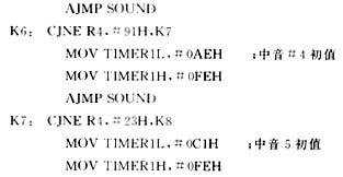
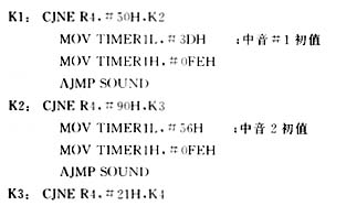


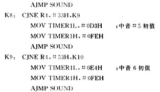

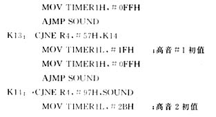

(3) The block diagram of the timer 1 interrupt service is shown in Figure 3. 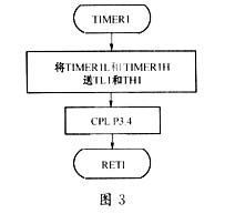
Timer 1 interrupt service routine: 
(4) The block diagram of the keyboard scanning program is shown in Figure 4.
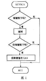
Keyboard scanner: 
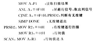
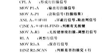

4 Conclusion This article introduces the method of designing a miniature electronic organ with a single-chip microcomputer. As long as the various programs in this article are serially written, it is a complete 16-key micro-electronics program. Interested readers can design a miniature electronic keyboard with more keys, or even micro The keyboard adds the function of playing demo songs [1]. If you have a higher programming skill, you can program and record the time of the button to make a miniature keyboard with recording function.
Single Phase Vfd,220V Frequency Inverter,Ac Frequency Inverter,High Frequency Inverte
WuXi Spread Electrical Co.,LTD , https://www.vfdspread.com