The most attractive millimeter wave applications today are mainly in the E and V bands. The E-band corresponds to a frequency range of 60 GHz to 90 GHz, in which only the line-of-sight transmission (LOS) method can be adopted due to the influence of atmospheric attenuation. In fact, many molecules in the atmosphere, such as oxygen, water vapor or nitrogen, can absorb energy at specific wavelengths in this band. However, in practice, sufficient spectrum resources available over these frequency ranges are still driving the industry to apply future technologies to these frequency ranges. Similarly, the V-band corresponds to 40 GHz to 75 GHz and is widely used for satellite communications.
There are three key applications being developed in these bands: mobile backhaul, automotive radar, Wi-Gig (ad).
The first application relies on the fact that the current hyper-heterogeneous network is filled with multiple small base stations, greatly increasing the need for transmission capacity of the return line. The core network must process a large amount of data to be transmitted to each node in a particular area. Therefore, based on these connections of millimeter-wave wireless links with bandwidths greater than 1 GHz, we can meet the backhaul requirements of modern and future networks and provide a solution that is more than fiber. Mobile backhaul and automotive radar are the most important applications. The 79 GHz band will most likely be the standard frequency for FMCW (Frequency Modulated Continuous Wave) radar technology. The technology can operate with signals up to 4Ghz bandwidth to achieve the required accuracy when detecting targets in a mobile environment. Finally, Wi-Gig is a new WLAN 802.11 standard that has been developed for very high-rate transmission services such as uncompressed high definition television (HDTV) and instantaneous music and image transmission, which operates at 60 GHz. And occupy 2GHz bandwidth.
Given the characteristics of transmission at these frequencies, appropriate measuring instruments will be required to ensure the implementation of all of these technologies. These instruments will require an excellent dynamic range to handle highly attenuated signals and the ability to measure ultra-wideband signals.
2. Challenges of millimeter wave devices and different measurement schemes
2.1, harmonics
Harmonic mixer equipment works in such a way that the limited local oscillator (LO) frequency involved in the mixing process is affected by harmonic components. The main advantage of using these types of mixers is the simple and cost effective solution it provides.
However, there are two main problems from these systems. First, the multiple harmonics that are used to affect the local oscillator signal introduce losses proportionally as the frequency increases. Therefore, the dynamic range of the solution becomes very poor. Second, the impact of the mirroring reaction is important here because multiple frequency components are not welcomely mixed in during the process. The most influential image response on the measurement results is displayed at the 2x offset position of the intermediate frequency (IF). As an example, if one spectrum plus one harmonic mixer designed to operate at the 1.58 GHz IF frequency measures the 4 GHz bandwidth signal from the FMCW radar, some important test items such as frequency error, occupied bandwidth, or The transmit power will not be measured because there will be a mirrored response that overlaps with the actual radar signal. In some cases, this problem may be solved by the image suppression method. However, this solution is ineffective in the case of FMCW frequency modulated continuous wave modulation because the transmission frequency is constantly changing.
2.2, typical down conversion configuration
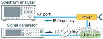
A typical way to overcome the image response of a harmonic mixer based solution is to connect to the spectrum analyzer using a classic downconversion setting. On the one hand, due to the configuration used by the basic mixer, harmonics are not used to affect the local oscillator signal. An ideal IF frequency can be designed according to the bandwidth to be tested and the bandwidth. Basically, a continuous wave combined with a multiplier will provide the required local oscillator signal to the downconverted signal.

On the other hand, a system needs to be composed of multiple components such as a mixer, a local, a multiplier, a filter, and a gain amplifier. Obviously, since the above devices need to be configured, calibrated, and maintained in use, it can be understood that the down conversion configuration can be time consuming.
2.3, high performance basic mixer
The figure below shows the idea of ​​Anritsu's high performance basic mixer. The MA2808A and MA2806A, which operate in the E-band and V-band, respectively, can be understood as an integrated downconverter, based on waveguide technology and built-in single-stage multiplier, low-noise amplifier, and filter design. These devices provide a solution to the problems discussed earlier: they have excellent dynamic range, and the mirroring reaction takes place far away from the required signal, and they only need one connection to work with the spectrum analyzer.

On the one hand, high-performance basic mixers have two main benefits compared to harmonic mixers: better sensitivity or DANL, thanks to lower conversion losses; and better image rejection, benefit Use 1.875GHz intermediate frequency. In addition, internal mixing/filtering techniques and a unique polarization transfer feature make millimeter-wave signals measuring 4 GHz bandwidth feasible. On the other hand, high-performance basic mixers have the following advantages over traditional downconverters: they allow a simple configuration or connection to a spectrum analyzer, and conversion losses can be easily added from USB memory through a single-button operation, providing a Better 1dB compression point performance than common downconverters. Undoubtedly, this compact test system simplifies the layout of the design and manufacturing site while reducing the maintenance and calibration costs of the measuring instrument.
3. Typical measurement items for millimeter wave equipment
Measurements of millimeter-wave devices can be divided into two distinct parts: RF output characteristics (following ETSI EN 302 264-1) and modulation or signal characteristics (depending on the technology to be tested). In the next section, we will explain how Anritsu's high-performance millimeter-wave solution demonstrates its outstanding advantages in each section.
3.1. Transmit power, frequency error and stray radiation with sufficient sensitivity
In many cases, due to the nature of the signal at these frequencies - greatly affected by reflections, attenuation or material absorption, the transmit power and spectral emission templates of millimeter wave devices need to be tested under Over The Air (OTA). Therefore, test equipment needs to have good sensitivity. For example, if the test antenna is 50 cm from the device under test, the free space loss of the 79 GHz signal will be around 65 dB. Since the Maximum Radiation Average (EIRP) requirement defined by ETSI EN 302 264-1 measures "-40 dBm / MHz, considering the test antenna gain of 23 dBi, the requirement for the test equipment at 79 GHz will be approximately 142 dBm / Hz.
In general, a typical harmonic mixer is characterized by a conversion loss of approximately 15 dB to 20 dB. When combined with a spectrum analyzer, we can estimate the display average noise level (DANL) to be between -135 dBm / Hz and 140 dBm / Hz, which makes it difficult to meet the above requirements. However, the new MS2840A spectrum analyzer with excellent noise floor performance combined with the MA2808A high-performance base mixer requires at least 8dB of sensitivity for transmit power and spurious emissions.
3.2, broadband modulation test
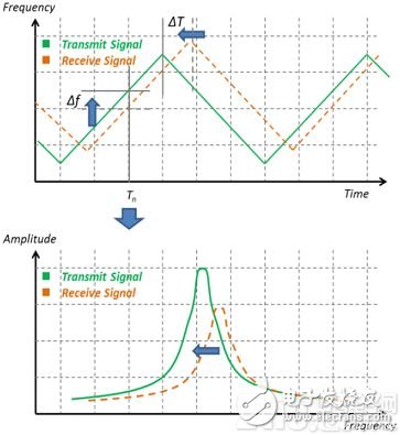
To measure millimeter wave quality, the phase noise performance of the spectrum analyzer is very important. For example, when testing an FMCW automotive radar, the phase noise characteristics and the frequency linearity of the device under test must be verified. When the difference between time and frequency between the transmitted and received signals is small, the phase noise performance of the spectrum analyzer is poor, because the received signal may be hidden in the phase noise of the transmitted signal, and the two signals cannot be distinguished, as shown in the following figure. Show.

The MS2840A combined with the MA2808A achieves excellent phase noise performance below -100 dBc (100 kHz offset) and below -110 dBc / Hz (1 MHz offset) at 79 GHz to meet automotive radar technology of at least -90 dBc / Hz Phase noise performance requirements (100 kHz offset) and -100 dBc / Hz (1 MHz offset).
4, summary
With the promotion of the upcoming 5G network and ADAS, the demand for millimeter wave systems is also growing. To test these ultra-wideband technologies, spectrum analyzers with external mixers must avoid image response problems, must provide sufficient sensitivity for OTA testing, and must have sufficient modulation phase noise performance for modulation analysis. The combination of the MS2830A/MS2840A spectrum analyzer and the MA2808A high performance waveguide mixer is the ideal solution to meet these needs.
Travel Charger Adapter is convenience for these people who always travel in many countries. Desktop Power Adapter have normal DC connector for your need, and wall power adapter have mutil plug, like US/UK/AU/EU etc. We also can produce the item according to your specific requirement. The material of this product is PC+ABS. All condition of our product is 100% brand new.
Our products built with input/output overvoltage protection, input/output overcurrent protection, over temperature protection, over power protection and short circuit protection. You can send more details of this product, so that we can offer best service to you!
Travel Charger Adapter,Portable Travel Charger Adapter,Mini Travel Charger Adapter,Travel Charger Supply
Shenzhen Waweis Technology Co., Ltd. , https://www.waweisasdapter.com