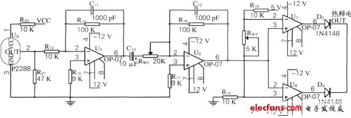
Figure object positioning detection circuit schematic
The signal is input to the dual-limit comparator after the second-stage op amp, where RW3 is used to adjust the amplification of the second-stage op amp, and RW4 is used to set the two threshold levels Uref1 (at U7) and Uref2 (at U8). When the detection voltage is greater than Uref1, U7 outputs a high level, U8 outputs a low level, then D2 is turned on and D3 is turned off, pyroelectric OUT is high level; when the detection voltage is lower than Uref2, U7 outputs a low level. When U8 outputs a high level, D2 is turned off and D3 is turned on, and pyroelectric OUT is high. When the detected voltage is between Uref1 and Uref2, both D2 and D3 are turned off, and the pyroelectric OUT is low. The amplified and shaped signals are input to the microcontroller.
Wuxi Juxingyao Trading Co., Ltd , https://www.juxingyao.com