Luxeon high-power LEDs are much better than ordinary low-power LEDs in terms of heat dissipation. The electrical and thermal channels are separated. Its LED chips are connected to a metal insert, and the heat dissipation performance is greatly improved.
However, high-power LEDs are used in special lamps or in lamps used in harsh environments. The protection level of these lamps is generally above IP65. If the casing is made of non-metallic (such as plastic) material, although the LED is connected to the aluminum substrate ( MCPCB), but if the heat on the aluminum substrate can not be effectively conducted to the surface of the casing, the heat accumulated will cause the temperature of the aluminum substrate to rise sharply, resulting in excessive temperature, increasing the possibility of LED failure, resulting in increased LED light decay. The life is shortened.
Theoretically calculating the heat dissipation of the lamp, the heat conduction theory of the lamp has many difficulties. The main difficulty is that conduction and convection play a role in heat conduction at the same time, while convection is convection in a closed cavity, and the boundary conditions are very complicated; conduction is also passed. Multi-layer thermal conductive materials, multi-layer interfaces, the cross-sectional area is usually unequal, and the heat flow line distribution is difficult to obtain by analysis before calculation.
Since the luminaire gradually heats up after being turned on, and finally reaches a thermal stable state, that is, the temperature at each point is the highest in the thermal stable state, the heat dissipation calculation of the luminaire generally only considers the steady state condition, and the transient temperature distribution is not important. The heat conduction of a steady state heat source in an isotropic single medium is subject to the Poisson equation [1]: where is the thermal conductivity of the medium, which is the heating power of the heat source.
Since the structure of the luminaire is a variety of media, in the actual calculation, it is necessary to solve the above formula one by one for each medium, and it is very difficult to calculate the temperature field distribution in the luminaire, and it is not necessary. In fact, what we are concerned about is whether the temperature of certain parts is within the tolerable temperature range, as long as the temperature at which these parts reach thermal stability is calculated.
In this paper, the thermal resistance algorithm of the efficiency circuit is discussed. The advantage of the thermal resistance algorithm is that it does not need to know the exact ambient temperature, nor does it have to solve the temperature field in the luminaire, and directly calculate the temperature rise of the focus in the luminaire. The difficulty is the heat flow line. Distribution must be obtained through analysis rather than calculation, which is often complicated.
The thermal resistance algorithm of the equivalent circuit is illustrated by an example calculation.
The basic structure required for the luminaire is as shown in the figure below. The LED is in a sealed plastic casing. The heat insulation layer on the right side is thicker. Compared with other parts, the heat conduction is basically negligible. The heat is mainly passed through the support frame, the plastic casing and the rubber jacket. Convection into the air by external air convection.
1. Simplify the model:
(1) The aluminum substrate is considered to be an isothermal heat source;
(2) an additional heat conducting layer between the support plate and the aluminum substrate;
(3) Since the thermal conductivity of plastic is much higher than the thermal conductivity of air, the heat conduction of air is negligible;
(4) An additional layer of thermal conduction between the support plate and the plastic case
(5) Close contact between the plastic case and the rubber outer skin
(6) The convective heat conduction between the aluminum substrate and the outer casing is negligible [2]
Therefore, the total thermal resistance is the thermal resistance of the additional thermally conductive layer between the support plate and the aluminum substrate;
The thermal resistance of the support plate;
The thermal resistance of the additional thermally conductive layer between the heat sink and the plastic housing;
Thermal resistance of the plastic case;
The thermal resistance of the rubber sheath;
The thermal resistance of the rubber skin to convective heat transfer in the air [1].
The following table is the comparison between the two structural temperature tests and the theoretical calculation results. Support frame structure Electrolytic copper heat sink structure Ambient temperature (°C) Aluminum substrate temperature (°C) Ambient temperature (°C) Aluminum substrate temperature (°C)
Theoretical calculation 401264064.6
Test 39.5127.339.872.3
3. Discussion From the above calculations, it can be seen that the thermal resistance calculation method equivalent to the circuit is used to select a suitable simplified model. For the temperature rise of the temperature concern point in different heat conduction structures, the heat conduction structure can be judged before the mold is opened. Inferior, at the same time, the main structural improvement direction can be judged according to the calculation results of the thermal resistance of each part, which has practical significance for guiding and improving the structural design.

Main Features for Flame Retardant Tape
Flame Retardant/ Environmental Friendly
Made from High Performance PVC
Consistent Stretch
Cold & Weather Resistant
Professional electrical industry Grade
Can also be used for colour coding, arts and crafts
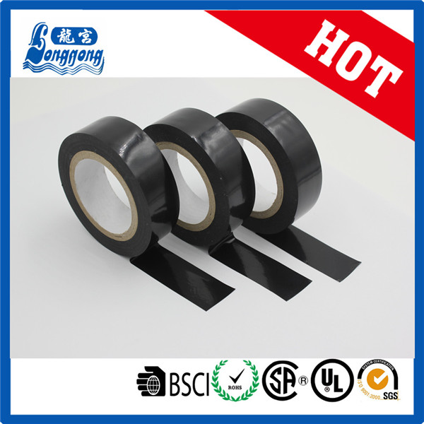
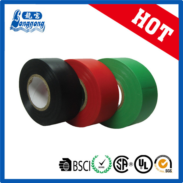
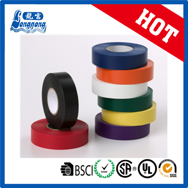
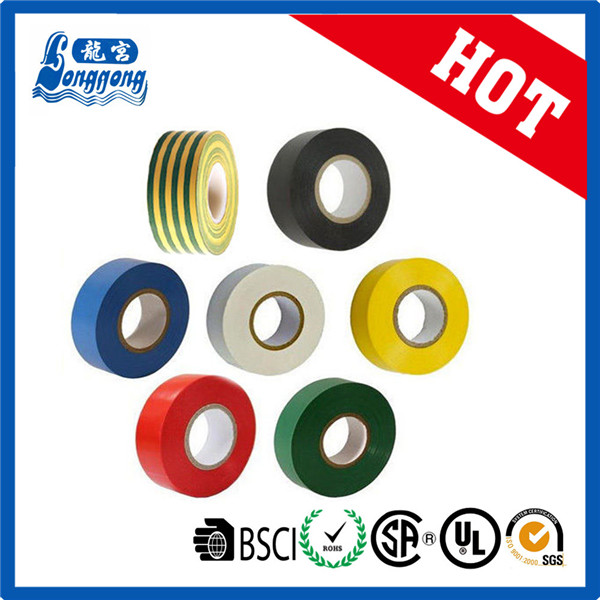
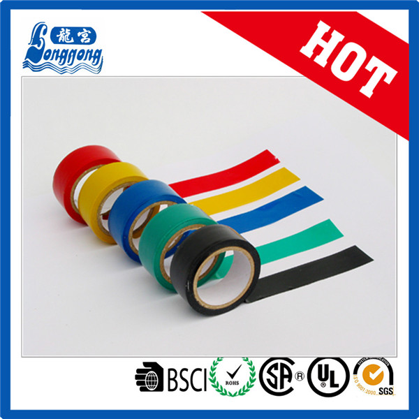
Applications for flame retardant tape
can be used for insulative connection,phase labeling,sheath protection and colligation of wire and cable under the voltage of 600V and on the environment temperature between 00C~800C.It can also be used for bandaging,fixation,splicing,remedy,
encapsulation and protection in the industry. Flame Retardant or No Flame Retardant.
Flame retardant tape specification:
Thickness: 0.10-0.20 mm
Adhesive: rubber
Adhesion: 1.6/1.8 N/cm
Tensile strength: 16/18/28 N/cm
Elongation: 160%
Voltage breakdown: 6.5/6.8/8.0 KV
PACKING FOR Pvc Tape:
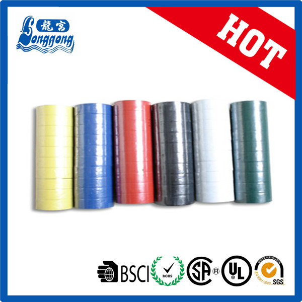
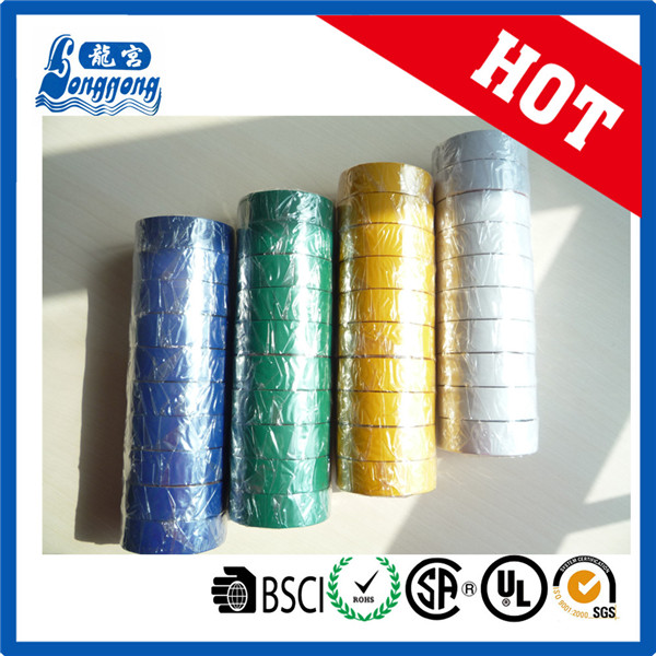
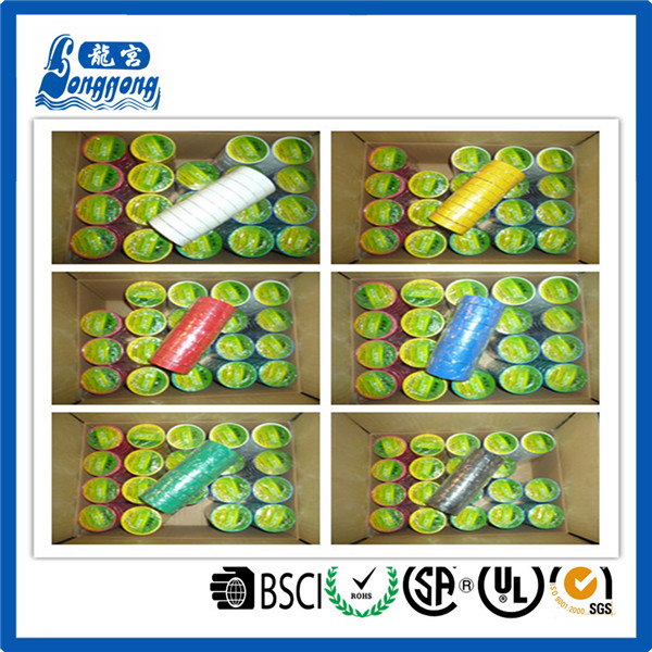
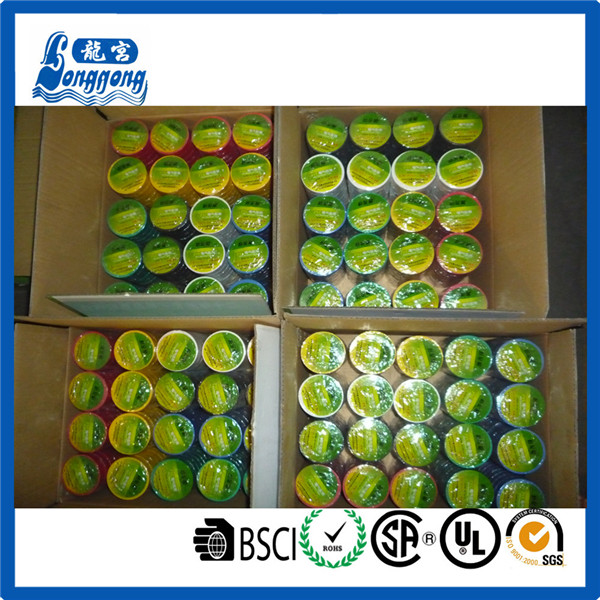
Flame Retardant Tape
Fr Pvc Tape,Flame Retardant Tape,Flame Retardent Tape
Shijiazhuang Longgong Plastic Products Co., Ltd. , http://www.pvctapemanufacturer.com