In China's new "Road Traffic Law", in order to maintain road traffic safety, the driving speed and continuous driving time are also clearly stated. Some foreign transportation developed countries have also formulated national unified regulations in this regard. Fatigue driving is a “stealth killer†on road vehicles, especially on highways. According to relevant statistics, the conclusions drawn from a large number of case studies of traffic accidents suggest that road traffic accidents caused by fatigue driving account for traffic accidents 20% of the total. Fatigue driving accounts for 22%-30% of the causes of death traffic accidents, ranking first among the causes of death traffic accidents, and thus can be considered to be harmful to road traffic safety.
This article refers to the address: http://
In addition to regulatory construction, domestic and foreign automobile manufacturers have also designed various instruments and equipment for fatigue driving monitoring. An infrared eyeball scanner for fatigue driving has been successfully developed in the United States. This eyeball scanner is shaped like a small camera. It is also very convenient. Just install it on the instrument panel and let the lens aim at the driver. The scanner will continuously send infrared signals to scan the white part of the driver's eyeball, and at the same time judge the degree of fatigue and issue a “deceleration stop†and “rest. "Ask" and other warning signals. Renault, Nissan and other industrial giants have long-term research and development to overcome fatigue driving. A surveillance system is still not commercially available due to the application of theoretical technology. The fatigue alarm device developed by Toyota Japan can detect these reactions as long as the driver is a little sluggish when manipulating the steering wheel, or the pulse changes a little, and warns the seat cushion to vibrate or brake automatically.
The fatigue tester developed by the University of Tokyo in Japan can be worn on the driver's wrist. The tester is equipped with a small oxygen cell electrode that measures the lactic acid, ammonia and alcohol content of the driver's sweat and then transmits the data to the research center via a small radio transmitter. Through research and analysis, the research center determines the driver's fatigue level and promptly warns the driver to avoid traffic accidents. There are also reports in China that can effectively prevent drivers from driving illegally and curbing major traffic accidents.
These methods have certain difficulties in achieving practical problems due to one or the other problems. With the rapid development of electronic technology, ARCHEAN.net copyright, through the use of the most advanced testing technology, combined with the application of embedded computers, network technology, intelligent control technology, monitoring the fatigue driving state of the car, to reduce the fatigue caused by driving The purpose of road traffic accidents.
Design overview
The goal of this design is to apply the latest developments in modern electronic technology, using Motorola's chip and sensor for the fifth embedded microprocessor "Freescale Cup", designing the driving state based on MM908E625 and Low-G (fatigue driving) Monitor.
Monitor features:
1. Multi-point monitoring of the steering wheel, accelerator pedal and brake pedal of the steering wheel.
2. Acceleration sensor signals are processed independently to ensure real-time performance.
3. The LIN bus network realizes distributed electronic system control in automobiles.
4. Interactive platform: driving road conditions are more conducive to control system monitoring. Provide sound and light, vibration alarm tips.
5. Large-capacity data storage and acquisition, large-screen LCD display, data query for different driving time segments.
6. Neuron network technology, fuzzy control and expert systems.
The basic idea of ​​the vehicle driving state (fatigue driving) monitor is that when the driver is driving normally, driving short distances, driving for a short time, there is no fatigue driving problem. At this time, the work of the monitor is to collect data on the driving habits of the driver. Establish a mathematical model of driving habits and correct it based on continuously collected data.
As the continuous driving time increases, the monitor automatically enters the fatigue driving monitoring state. If the driver has fatigue symptoms, it will inevitably reflect a deviation from normal driving. For example, the frequency of sudden sudden braking increases, the steering wheel suddenly turns continuously when the throttle is large, and the smoothness of the accelerator pedal changes. Combined with neural network technology, fuzzy control and expert system, it composes the monitoring of the driver's driving state, increases the interactive platform with the driver, and presents driving instructions and alarms to the driver. I have made some attempts on my own automatic car and achieved results.
The acceleration sensor Low-G is installed on the steering shaft, the accelerator pedal and the brake pedal of the steering wheel respectively, and the signal of the sensor is processed by the MCU/DSP embedded microprocessor MM908E625 to form a LIN bus network.
In addition to the acceleration sensor Low-G, the sensor requires a speed and position sensor.
Hardware description
1. Hardware system composition:
The main node of the system is an embedded PC, and the PIII processor and touch screen are provided to provide an interactive interface. The main node PC completes database establishment and update, intelligent control program operation and communication management of LIN sub-nodes. The interactive interface provides selection of road sections, road conditions, measurement and control time, level warnings and alarms for driving status.
The master node is connected to four LIN sub-nodes via the LIN interface board. The LIN sub-node uses the MM908E625 as the core to detect and signal the physical quantities such as acceleration, engine speed, vehicle speed, throttle opening and brake pedal position. The first, second and third sub-nodes independently process the steering wheel, the accelerator pedal and the brake pedal acceleration sensor Low-G signal. The fourth LIN sub-node uses Hall-type sensors for engine speed, vehicle speed, throttle opening and brake pedal position, engine speed and vehicle speed, Hall pulse sensor, throttle opening and brake pedal position.
Experiments show that the acceleration signal can better reflect the different control effects of the steering wheel, the accelerator pedal and the brake pedal of the steering wheel of the vehicle during normal driving and fatigue driving, and the output of the acceleration signal during normal driving. The voltage changes at a center point voltage of ±0.5V, while the output voltage of the acceleration signal during fatigue driving changes at a center point voltage of ±1V, and the frequency of the acceleration signal changes is greater than that of normal driving.
The measurement signal of the fourth LIN subnode is used as an input qualification for the fuzzy controller.
The hardware system block diagram is shown in Figure (1):
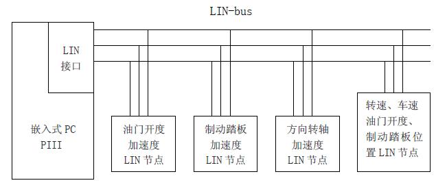
Figure (1) hardware system block diagram
2. Accelerometer LIN subnode:
(1). Speedometer LIN sub-node schematic (2) and acceleration measurement module diagram (3):
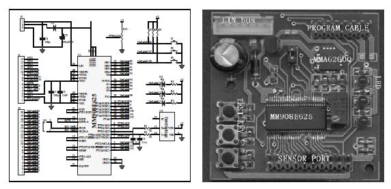
Figure (2) LIN sub-node schematic diagram (3) measurement module
(2). Design and structure installation of accelerometer LIN sub-node:
The MMA6260Q is an XY dual-axis sensor. To ensure optimal acceleration measurement, the accelerometer is designed as a measurement module with a LIN interface and a physical size of 5X5X2CM. It is directly mounted on the accelerator opening pedal, brake pedal and direction shaft. The accelerator opening pedal and the brake pedal measuring module are vertically installed to ensure that the acceleration signal of the pedal can be measured in the X-axis direction, and the average vibration signal in the vehicle operation is measured in the Y-axis direction. The directional axis measurement module is mounted horizontally to ensure that the XY axis direction measures the acceleration signal of the steering wheel steering.
3. Introduction to the sensor:
In addition to the Low-G for acceleration measurement, the following sensors are available.
Throttle (throttle) opening sensor: The throttle is operated by the driver and directly reflects the driver's control intention, so it is an important signal to judge the engine operating conditions. The throttle position sensor is mounted at the end of the throttle shaft and uses a Hall linear sensor. After being processed by the sensor signal conditioning board, the LIN sub-node measurement module detects the search enterprise network. When the throttle valve is completely closed, the sensor output voltage is equal to 0V; when the throttle valve is fully open, the output voltage is equal to 5V. When the throttle is not broken, its output voltage increases linearly.
Engine speed, vehicle speed sensor: Hall pulse type. After being processed by the sensor signal conditioning board pulse shaping circuit, pulse capture is performed by the input capture port of the main chip. Corresponding to the range of engine speeds from 1500 rpm to 8000 rpm, the interface board output corresponds to a 0V-5V change. Corresponding to the range of vehicle speed 60KM/h-180KM/h, the interface board output corresponds to 0V-5V change.
Intelligent control (fuzzy controller) design
The object of vehicle driving state (fatigue driving) monitoring is a rather complicated system control problem, which belongs to the category of multi-input-multi-output fuzzy control system. People's driving habits, different road conditions, different driving times reflected in the handling of the vehicle, will produce quite different car driving conditions.
Various vehicle control, as input, is expressed as throttle (throttle) opening, brake pedal position, engine speed, vehicle speed change, speed change (ie acceleration), steering wheel steering angle and angular acceleration, etc. . The vibration generated by the vehicle under different road conditions as the input quantity will also affect the measurement of the sensor, especially the impact of the acceleration sensor. The vibration signal is measured by the LIN sub-node measurement module according to the "average vibration signal strength" in the signal pre-processing procedure. Weaken or eliminate. As the output amount, it is expressed as the quality of the driving state of the vehicle, and is classified into three levels of "good", "medium", and "difference". When designing the control rule base, the multi-input-multi-output fuzzy control is structured into a multi-input-single-output fuzzy control structure, and then the single-input-single-output fuzzy control system is designed to realize the fuzzy decoupling of the multivariable control system. .
The experimental data shows that the fatigue driving phase is reflected in the driving state of the car, which is manifested by the change of the acceleration signal of the throttle (throttle) opening, the brake pedal and the steering wheel steering than the acceleration signal of the normal driving period. Values ​​and frequencies are significantly different. This topic uses FreeScale's Low-G series biaxial acceleration sensor MMA6260Q, which can accurately and real-time capture the required acceleration signal, which is an important parameter of the input variable of the fuzzy controller.
Early research on fatigue driving in this research topic mainly measures parameters such as throttle opening, brake pedal position and engine speed, and vehicle speed. These parameters reflect the change of driving state indirectly and laggingly. These parameters can be used as fuzzy controllers. In the definition of various driving states, combined with the measurement of acceleration, fuzzy control rules are established.
Three sets of fuzzy controller models are established corresponding to the three types of variables: throttle opening, brake pedal position and steering wheel steering axis. The following describes the design of the fuzzy controller with the throttle opening as a variable.
1. Pasting process:
The input amounts of the throttle opening degree fuzzy control are the accelerator opening degree s, the engine speed n, the vehicle speed v, and the accelerator opening acceleration a. The acceleration is divided into five levels of “negative large NBâ€, “negative small NSâ€, “zero ZEâ€, “positive small PSâ€, and “Zhengda PB†(ie, five fuzzy subsets). The output of the controller is the quality of the driving state of the vehicle (indicated by H), and is divided into three levels: "good GOOD", "medium MIDDLE", and "poor BAD". In order to achieve the fuzzification, the membership function of the fuzzy opening subset of the throttle opening acceleration a is determined as shown in the following figure (4). In order to perform fuzzy reasoning according to certain linguistic rules, the membership function that determines the output quantity, that is, the quality of the driving state, is shown in the following figure (5).
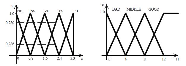
Figure (4) Acceleration a membership function graph (5) driving state membership function graph
2. Establishment of fuzzy control rules:
Corresponding to the establishment of the throttle opening fuzzy control rule base, it has interactivity and correlation with the values ​​of the throttle opening s, the engine speed n and the vehicle speed v in different numerical ranges. The establishment of the rule base needs to continuously collect data in the running of the program, and through the self-learning determination method and the self-adjustment of the fuzzy rules, it is constantly revised and improved during the experiment.
The fuzzy control rules focus on the working process of the "poor" and "medium" that affect the driving state of the vehicle. Among them, the "poor" driving state rule corresponds to the throttle opening s divided into 0, 1, 2-9 a total of ten segments, the engine speed n is divided into 1000rpn, 1500rpn-5500rpm a total of ten segments, the vehicle speed v is divided into 60km / h, There are ten segments of 70km/h-150km/h, and the acceleration is divided into five levels: “negative large NBâ€, “negative small NSâ€, “zero ZEâ€, “positive small PS†and “Zhengda PBâ€, which can be summarized as effective. Control rules 86 rules.
Fuzzy control rule (L) formula: if (IF) throttle opening s is x segment [and (AND)] V [or (OR)] engine speed n is y segment [and (AND)] V [or (OR) When the vehicle speed v is z-segment and the acceleration is level m, the (THEN) driving state is "S".
3. Accurate calculation:
Corresponding to the results obtained by the above reasoning method, combined with the database analysis established by the data collected during normal driving of the vehicle, the frequency of occurrence of the acceleration level is accurately calculated according to the membership function of the output fuzzy subset to determine the optimal driving state of the vehicle. Inferior "poor" and "medium" provide operational prompts and alarms from the interactive interface.
Software description
1. Database establishment:
The establishment of the driving state fuzzy controller database and the data update are important parts of the design of this topic. When the car is driving normally, the system is set to drive for the first two hours of continuous driving, during which time monitoring The work of the instrument is to collect data on the driver's driving habits, and to linearize and quantify the data according to the set quantization level, corresponding to different dimensions of the three types of variables: throttle opening, brake pedal position and steering wheel steering axis. The data is processed according to the scale factor, and the data is blurred according to the membership function of the fuzzy subset.
In order to eliminate large errors, an interpolation operation is used between the quantization levels, and a weight coefficient factor w(.) is introduced, and the value of the ambiguity is obtained by two adjacent discrete weighting operations for any one continuous measurement value. Based on the fuzzy data creation database, a mathematical model of normal driving habits is generated and corrected based on the continuously collected data. As the continuous driving time increases (more than two hours or the change in the collected data exceeds the driving state monitoring indicator), the monitor automatically enters the fatigue driving monitoring state.
2. Software block diagram
(1). PC program design:
The PC program is written in C language, which completes the establishment and maintenance of the database, the management of the LIN-BUS network, the operation of the fuzzy controller algorithm and rules, and the input and output control of the interactive interface. The software block diagram is shown in Figure (6).
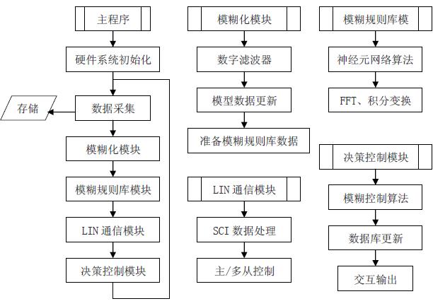
Figure (6) PC software block diagram
(2). Measurement module programming:
The measurement module is a data acquisition device with MM908E625 microcontroller as the core. The program is designed with CodeWarrior3.1CW-HC083.0. The software block diagram of the measurement module is shown in Figure (7).
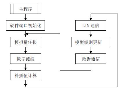
Figure (7) Measurement module software block diagram
in conclusion
The application of intelligent control technology to automotive fatigue driving monitoring is a rather complicated and quite difficult research direction. Through the research of LIN-BUS network, MM908E625, Low-G accelerometer and other sensors are built with embedded PCs. A hardware platform that realizes the establishment of a database for normal driving, short-distance driving, short-time driving, correction of rule base data, and fatigue driving state monitoring. The fuzzy controller is designed for three factors that mainly affect the driving state, such as throttle opening, brake pedal position and steering wheel steering shaft. It has been usefully discussed from both theoretical and hardware implementations, although it has practical application and industrialization. A certain distance, but laid a good foundation for further improving the design of the system.
Gasoline Generator,Fule Tank Generator Set,Silent Trailer Diesel Generator,Small Diesel Power Generator
XCMG E-Commerce Inc. , https://www.xcmg-generator.com