The 89C51 chip does not have its own PWM generator. If you want to use 51 to generate PWM waves, you must use software programming to simulate. The method can be roughly divided into two methods: software delay and timer generation. The following will be introduced one by one.
1 software delay method
The software delay function is used to control the duration of the level to achieve the effect of simulating pwm.
The procedure is as follows:
#include
Sbit pwm=P1^0;
Main()
{
While(1)
{
Pwm=1;
Delayus(60); / / set high level delay 60us, duty cycle 60%
Pwm=0;
Delayus(40);
}
}
Void delayus(uint x)
{
While(x--);
}
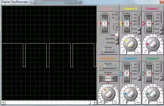
The proteus software simulation results are as follows:
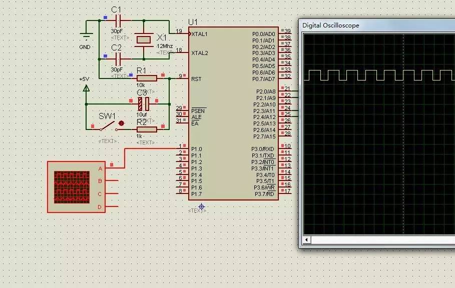
It can be seen that the pwm output can be simply simulated by this delay function method. But the shortcomings of this method are also quite obvious. When the program needs to perform other operations such as keyboard scanning and display operations in addition to the pwm wave output, it needs to occupy a certain machine cycle of the CPU, which will affect the accuracy of pwm. This method is rarely used now, and the next step is to introduce the more common methods.
2 timer generates pwm
This method utilizes the timer overflow interrupt, which changes the level of the interrupt service routine, and can output a more accurate pwm waveform when the program is more complicated and multi-operation.
2.1 Precautions
2.2.1 The contents of the interrupt service routine.
Generally speaking, the interrupt service program only completes the function of changing the flag bit and converting the high and low levels. If there are too many operations in the interrupt service program, the output of the pwm wave will be affected. In particular, the division, the remainder, and the floating point operation will occupy a large amount of Machine cycle, the operation should be completed outside the interrupt.
2.2.2 The problem of loading the initial value of the timer.
The initial value of the load cannot be too close to the overflow value of the timer. If we use timer mode 1, we can count up to 65536. If we assume that the initial value is 65534, then the timer counts two numbers and it will enter the interrupt, which will make the program disorder and other functions cannot be executed normally. Therefore, it is generally necessary to leave a margin of 50-100.
2.2 How the timer works
In the selection of the working mode of the timer, the working mode of the timer can be selected as 0, 1, and 2. The working mode 1 is used, that is, the 16-bit timer, so that a wider frequency modulation range can be obtained.
2.3 Calculation of the initial value of the timer
Let the duty ratio be α and the frequency be f
When the high level is generated, the value of the upper 8 bits of the timer should be loaded.
When the high level is generated, the value of the lower 8 bits of the timer should be
Obviously, the formula for generating a low level is as long as the α is replaced by (1-α).
However, in the 51 single-chip microcomputer, the floating-point operation needs to consume the CPU for a long time. In order to improve the program efficiency, the duty ratio is usually calculated by 100 times. At the same time, pay attention to the data type, avoid out of scope, and affect the calculation results. For the multiplication and division of C51, you can read the following article (click to read the original directly):
Http://blog.163.com/ssou_1985/blog/static/295320362010311102232210/
The revised formula is as follows:
a is 100 times duty cycle, fr is 0.01 times frequency
TH0 = (65535-a*100/fr)/256; //high initial value
TL0 = (65535-a*100/fr)%256;
Similarly, the formula for low level simply replaces a with (100-a).
2.4 routines
This routine uses the timer T0 to generate a PWM in the working mode 1, and uses the independent keyboard to control the frequency and duty cycle addition and subtraction, the frequency adjustable range is 100Hz-10kHz, the duty cycle is 0-100% (all theoretical values, Actual value is slightly lower)
Some of the code is as follows:
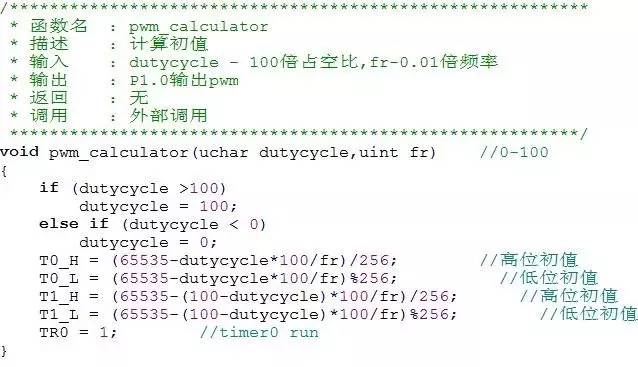
Note: T0_H, T0_L, T1_H and T1_L are used to temporarily store the initial value. After entering the interrupt service routine, the registers TH0 and TL0 are directly assigned to avoid the calculation in the interrupt.
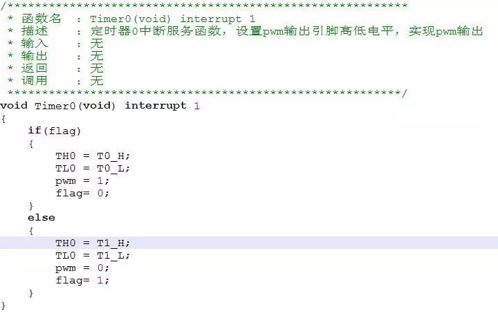
Note: flag is pwm output flag, flag=1 output high level, flag=0 output low level
Complete code please go to my network disk to download (invalid)
http://yunpan.cn/QzKaWM8VesFyc
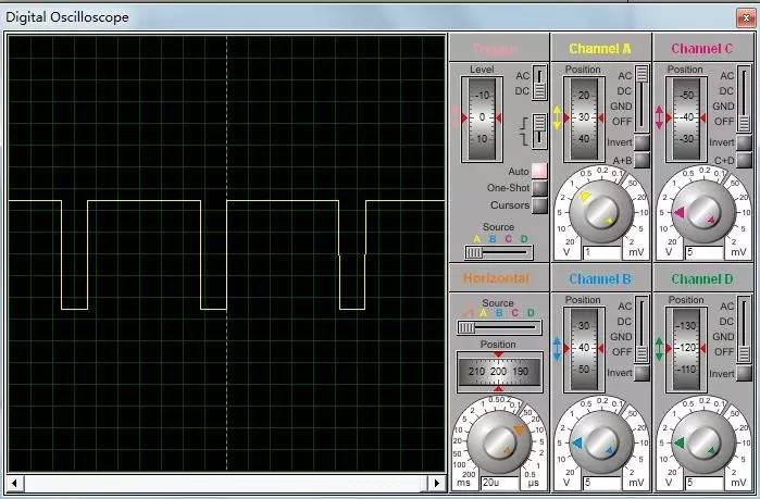
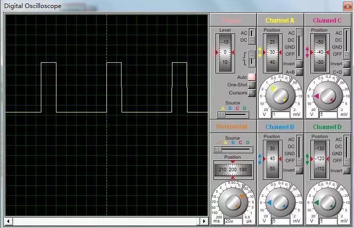
2.5 Software Simulation Results
2.5.1 frequency is 100Hz
a. The duty cycle is about 15%
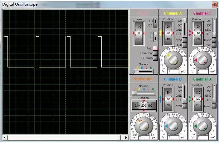
b. duty cycle 95%
2.5.2 Frequency is 10KHz
a. Duty cycle 15%
b. duty cycle 90%
Game machine harness advantages:
1).which is a full jamma harness with connectors for power supply, monitor, joysticks and buttons(microswitches).
2).It comes with edge connector, push button lugs, power lead, RGB monitor cable. Also includes extra button loom and connectors for all parts of your jamma.
3).We can make custom harnesses as customer request.
Game Harness,Blue Arcade Game Machine,Game Machine Wire Harness,Game Machine Harness
Dongguan YAC Electric Co,. LTD. , https://www.yacentercns.com