The easiest way to eliminate errors caused by wiring is to perform zero measurements. For DC voltage or resistance measurements, select the appropriate measurement range, and then connect the probes together and wait for a measurement—this is the case that is closest to zero input—and then press the null button. The readings obtained below will deduct the result of the zero measurement. Zero measurement is ideal for DC and resistance measurement functions. However, this technology is not suitable for AC measurements. The AC converter does not work well in the lower part of the range; the analog converters of the Agilent 34401A DMM do not specify specifications below 10% of full scale. The Agilent 34410A and 34411A digital multimeters use digital technology that can measure up to 1% full scale, but cannot be used to measure short circuits.
connectionIf you connect with different metals, it will form a thermocouple junction. Thermal junctions produce voltages that vary with temperature. Although this voltage is very low, but if you are measuring a small voltage, or your system has many connections, you need to take this issue seriously. This thermocouple junction can be considered at the DUT, at the relay (multiplexer) and at your DMM. Use copper-copper junctions to minimize this offset.
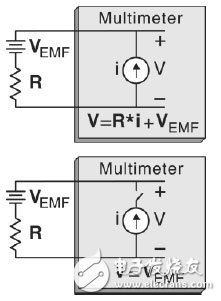
When making resistance measurements, you can use offset compensation to measure any offset voltage and subtract this error. Figure 1 shows two measurements made in the offset compensation measurement, the first measurement with a current source and the second measurement without a current source. Subtract the first reading by the second reading and divide it by the known current source current to obtain the actual resistance value. Since two readings are taken in the measurement, the reading speed will decrease, but the measurement accuracy will increase. Offset compensation can be used for both two-wire and four-wire resistance measurements.

figure 1
Use two measurements for offset compensation. The first measurement is the standard ohmic measurement; the second is the measurement of the offset produced by the thermoelectromotive force. The voltmeter reading is the difference between these two measurements divided by the known current source.
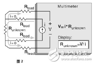
ConnectionThe four-wire Ohm method is the most accurate method of measuring small resistance. In this way, the test line resistance and contact resistance can be automatically subtracted. The four-wire resistance measurement connection is shown in Figure 2. Using a known current source and measuring the voltage generated by the resistor, the unknown resistance value can be calculated. An additional set of test leads is used to carry the current to an unknown resistor, and the voltage developed across it can be measured via a voltage sensing line. No current flows through the voltage sensing line, so it will not generate a voltage drop.

No current flows through the voltage sensitive line. The digital multimeter divides the measured voltage value by the known current to obtain the unknown resistance value.
Internal Digital Multimeter Offset
Automatic zeroing is used to eliminate the internal error source of the DMM. When autozero is enabled, the digital multimeter internally disconnects the input signal after each measurement, resulting in a zero reading. This zero reading is then subtracted from the subsequent measurement. This avoids the influence of the bias voltage on the measurement accuracy of the digital multimeter input circuit. Automatic zeroing in four-line measurements is always enabled, but you can disable it for faster measurement
With automatic zero function. When autozero is disabled, the digital multimeter takes a zero reading and then subtracts it from all subsequent measurements. Each time you change the function, range, or integration time, a new zero reading is taken.
Tip 2 Measuring Large ResistanceStable time effect
Capacitors in parallel with the resistors cause a settling time error after the initial connection and after the range change. The modern DMM inserts a trigger delay that gives the time for the measurement to stabilize. The length of the trigger delay depends on the selected function and range. These delays are sufficient for resistance measurements when the combined capacitance of cables and devices is less than a few hundred pF, but if there are parallel capacitors on the resistor, or if you measure resistance above 100 kΩ, the default delay may be not enough. Stabilization can take quite a long time due to the influence of the RC time constant. Some precision resistors and multifunction calibrators use capacitors in parallel (1000 pF to 100 μF), which together with the high-value resistors filter out the noise current injected by the internal circuitry. Due to the dielectric absorption (wetting) effects in cables and other devices, it is possible to increase the RC time constant and require a longer settling time. In this case, you may need to increase the trigger delay before testing.
Offset compensation when capacitance is present
If there is a shunt capacitor on the resistor, offset compensation may need to be turned off. When offset compensation takes the second reading without a current source, it will measure any voltage offset. However, if the device has a long settling time, there will be an error offset measurement. The DMM will use the same trigger delay for bias measurements in an attempt to avoid settling time issues. Increase the trigger delay is to make the device completely stable another solution.
High resistance measurement connection
When you measure a large resistance, insulation resistance and surface contamination can cause considerable errors. Various precautions must be taken to maintain the "cleanliness" of high-impedance systems. The test leads and fixtures are very sensitive to leaks caused by the moisture absorption of the insulating material and the "dirty" surface layer. Nylon and PVC are relatively poor insulators (1013 GΩ) compared to PTFE Teflon insulators (109 Ω). If you measure 1 MΩ resistance in wet conditions, the contribution of the leakage of nylon or PVC insulator to the error can easily reach 0.1%.
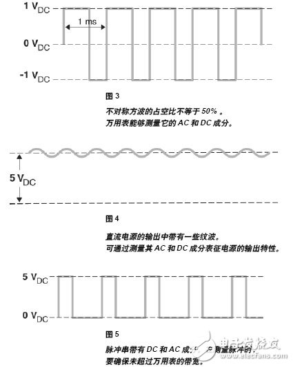
Tip 3 AC Measurement Using DC BiasMany signals contain both AC and DC components. For example, an asymmetric square wave contains these two components. Many audio signals also contain a DC offset generated by the DC bias current that is used to drive the output transistors. Some situations require measuring the DC+AC voltage, while others may only require the AC component. For this audio example, the amplifier gain compares the input AC voltage with the output AC voltage.
Most modern multimeters use a DC blocking capacitor in front of the AC RMS converter. It isolates the DC voltage and allows the multimeter to measure only the AC value. What is more important is that the multimeter can achieve the best measurement scale AC signal. For example, when measuring the AC ripple of a power supply, the multimeter isolates high-level DC and amplifies the AC signal according to the range selected by the AC component.
For the most accurate AC+DC measurement, these two components should be measured independently. The multimeter can achieve the best possible DC measurement by using a suitable range and suppressing the integration time of the AC component. When making AC measurements, select the appropriate range for the AC component. You can use the following formula to calculate the AC+DC RMS value:
True RMSAC+DC = √ (AC2 + DC2)
Agilent's new 34410A and 34411A use DC blocking capacitors for AC voltage measurements. AC's measurements use digital technology to achieve faster settling times and can handle higher peak factors, which are often encountered when measuring bursts. When measuring pulses, make sure that the pulses do not contain frequencies above the bandwidth of the multimeter. The 34410A and 34411A can measure AC signals up to 300 kHz. If the frequency of a large number of AC components is below 8 kHz, the 34410A and 34411A have a DC function with peak detection that accurately measures the DC and AC components. For higher frequency signals, you can measure the AC component separately and use the formula to calculate the AC+DC measurement result.

Most modern multimeters can measure AC signals down to 20 Hz. However, some applications require measuring lower frequency signals. To make such a measurement, you need to select the appropriate multimeter and perform the appropriate configuration. Please see the following examples:
The Agilent 34410A and 34411A multimeters use digital sampling technology for true RMS measurements down to 3 Hz. It numerically increases the settling time to 2.5 s in slow filters. For the best measurement, you should note:
1. It is very important to set the correct AC filter. The filter is used to smooth the output of an rms converter. At frequencies below 20 Hz, the correct setting is LOW. In the LOW filter setting, the stability of the multimeter is guaranteed by inserting 2.5 s delay. Use the following command to set the low filter.
VOLTage:AC:BANDwidth MIN
2. If you know the maximum level of the signal under test, set the manual range to help speed up the measurement. The longer settling time for each low-frequency measurement will significantly slow down the autoranging.
We recommend that you set the manual range.
3. The 34401A uses a blocking capacitor to block the AC RMS converter from measuring the DC signal. This allows the multimeter to measure AC components with the best range. When measuring a source with high output impedance, sufficient time is required to ensure the stability of the DC blocking capacitor. The settling time is not affected by the frequency of the AC signal, but it is affected by any change in the DC signal.
The Agilent 3458A has three methods for measuring the AC RMS voltage; its synchronous sampling mode can measure signals as low as 1 Hz. To configure the multimeter for low-frequency measurements:
1. Select synchronous sampling mode:
SETACV: SYNC
2. When you use the synchronous sampling mode, the input signal is DC-coupled for the ACV and ACDCV functions. In the ACV function, the DC component is mathematically subtracted from the reading. This is an important consideration because the combined AC and DC voltage levels can cause overload conditions even if the AC voltage itself is not overloaded.
3. Select the appropriate range to speed up the measurement because when you measure low-frequency signals, the auto-range feature causes delays.
4. To sample the waveform, the multimeter needs to determine the signal period. Use the ACBAND command to determine the pause value. If you do not use the ACBAND command, the multimeter may pause before the waveform repeats.
5. Synchronous sampling mode uses level-triggered synchronization signals. However, the noise on the input signal may cause false level triggers, resulting in inaccurate readings. It is important to choose the level that provides a reliable trigger source. For example, to avoid the sine wave peak, because the signal changes slowly, and the noise is very easy to cause false triggering.
6. To obtain accurate readings, make sure that the environment around you is electrically "quiet" and use shielded test leads. Enable level filtering, LFILTER ON to reduce the sensitivity to noise.
Configuration The 34401A can use the same configuration methods as the 34410A and 34411A. 34401A
The rms voltage is converted using an analog circuit with a blocking capacitor. It can measure signals as low as 3 Hz. To achieve the best measurement results, select a low-frequency filter, use a manual range, and verify that various DC biases are stable. When you use a slow filter, a delay of 7 s is inserted to ensure the stability of the multimeter.
Tip 5 Selecting a Sensor for Digital Multimeter Temperature MeasurementThere are four types of sensors commonly used for digital multimeter temperature measurements: Resistance temperature probes
(RTD), thermistors, IC temperature sensing devices, and thermocouples. Each has its own advantages and disadvantages.
Tip 6 Using Thermistors for Better SensitivityThermistors are made of semiconductor materials and offer high sensitivity, but they have a limited temperature range, typically -80°C to 150°C. The relationship between temperature and resistance of thermistors is non-linear, so the conversion algorithm is very complicated. Agilent multimeter with standard Hart-
The Steinhart approximation provides accurate transformation with a typical resolution of 0.08°C.
Tip 7 Use RTD for Better AccuracyResistance temperature detectors (RTDs) provide a very precise and highly linear relationship between resistance and temperature, with a measurable temperature range of approximately -200°C to 500°C. Modern multimeters such as the Agilent 34410A provide IEC 751 standard RTD temperature measurements with a sensitivity of 0.0385 Ω/°C.
IC temperature sensing devices generate a voltage that is linear with Celsius
Many manufacturers offer probes that produce voltage proportional to and degrees Celsius and degrees Fahrenheit. These probes typically use IC temperature sensing devices such as the NaTIonal Semiconductor LM135 series. This type of IC device can cover a temperature range of -50°C to +150°C. You can easily calculate the temperature according to the probe output displayed by the multimeter. For example, 270 mV is equivalent to 27°C.
Tip 8 Thermocouples for Extreme Temperature MeasurementsThe thermocouple can measure an extremely wide temperature range of -210°C to 1100°C. Its robust structure can meet the requirements of harsh environments. Unlike other types of temperature-sensing devices, thermocouples perform relative temperature measurements and therefore require a reference junction for absolute temperature measurement. But for most applications, adding an external reference junction is not practical. We recommend using the Agilent 34970A data logger and the 34901A 20-channel multiplexer with built-in reference junction. The 34970A also has a built-in temperature conversion algorithm for common thermocouples.
summary
To monitor a temperature, a thermistor and multimeter like the 34410A is a simple, low-cost solution. For accurate temperature readings, RTD should be used. A dedicated data logger is the best choice when monitoring multiple temperatures or high temperatures.
Tinned Copper Wire,Tinned Copper,Tin Coated Copper Wire,Tin Plated Copper Wire
Sowell Electric CO., LTD. , https://www.sowellsolar.com