The conversion of electromagnetic signals between different transmission media has always been an important part of microwave and millimeter wave technology research. In the millimeter wave band, in order to facilitate the connection between the test, the antenna and the independent microstrip circuit, it is often necessary to transition the microstrip circuit input and output ports through the conversion structure to the rectangular waveguide. When it is necessary to transmit a signal over a distance, the circuit is often converted from a microstrip to a waveguide to reduce transmission loss. Therefore, millimeter wave integrated circuits using microstrips often must include a waveguide-microstrip transition interface.
In practical applications, an additional factor that cannot be ignored in the transition is the airtight requirement. Many microstrip circuits, especially military microstrip circuits, have higher requirements for the airtightness of the system in order to ensure the stability of performance under various harsh environmental conditions. In addition, the current microwave and millimeter wave circuits are developing toward miniaturization. In order to facilitate the miniaturization of the overall circuit, the volume and interface direction of the transition device have also become an important consideration. At present, the conventional rectangular waveguide-ridge waveguide-microstrip transition, waveguide-microstrip probe transition and waveguide-to-polar fin line-microstrip transition structure can not solve the problem of airtightness well, and the opening on the waveguide is large. Larger perturbations will also occur for the field distribution within the rectangular waveguide. Waveguide-coaxial probe-microstrip transition is often used to solve the problem of airtightness. The general form is familiar to everyone. It is different from the traditional waveguide-coaxial probe-microstrip transition. On the basis of airtightness, the microstrip line is taken out from the through direction.
2 Basic principlesWe can think of the probe deep into the waveguide as an antenna. If the coaxial line is connected to the wave source, it radiates electromagnetic waves in the direction defined by the waveguide. Generally speaking, as long as the electric or magnetic field component of the electromagnetic wave is consistent with the electric field or magnetic field component of a certain mode of the waveguide. The model will be motivated. According to the reciprocity theorem, if the waveguide port is connected to the wave source, then the energy can also be coupled out from the waveguide. The probe is inserted from the short-circuit surface of the waveguide, perpendicular to the direction of the electric field in the waveguide, and the probe will affect the field structure in the waveguide (see Figure 1). Therefore, the energy cannot be coupled out, so it is necessary to Insert an adjustment screw directly above it to disturb the field structure in the waveguide (Figure 2). A capacitor is formed between the probe and the top surface of the screw, from which energy can be coupled out.
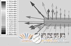
Figure 1 Electric field vector near the probe
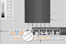
Figure 2 Electric field structure in the waveguide after inserting the adjustment pin
3 simulation designAccording to theoretical analysis, the position and length of the screw and the length of the probe are factors that affect the performance of the transition structure. Insert the probe from the middle of the short-circuited surface. Insert the adjusting screw from the middle of the wide side of the waveguide. The screw is located near the top of the probe tip. Set the radius of the adjusting screw to variable R1, the length of the adjusting screw to variable D, and the adjusting screw to short. The distance of the road surface is the variable C, the length of the probe is the variable L, and the radius of the probe is the variable R2. The model is built using Ansoft's commercial software HFSS. Adjusting these variables can get a better result as shown in Figure 4.
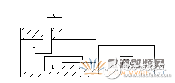
Figure 3 is a side cross-sectional view of the transition structure and the waveguide entrance view
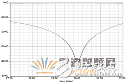
Figure 4 Transition structure optimization results
As can be seen from the figure, the transition structure has better performance at a frequency between 27G and 32G, and the insertion loss is less than 0.2 dB.
4 Production and testing of transitional structuresThe test was in a back-to-back format with two transition structures joined by a 15 mm long microstrip line.
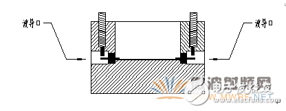
Figure 5 Test structure profile
The test instrument uses Agilent's 10MHz-40Hz vector network analyzer, and the adjustment screw is rotated to get the best transmission performance, as shown in Figure 6.
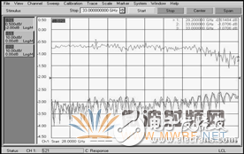
Figure 6 test results
It can be seen from the figure that in the frequency range of 28 GHz to 32 GHz, the return loss is less than -18 dB, and the insertion loss is less than 0.7 dB (including the loss of a 15 mm long 50 Ω microstrip line). The measured results are basically consistent with the simulation results, and the insertion loss is slightly larger than the simulation result, which is caused by the assembly error.
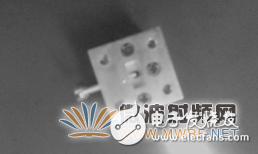
Figure 7 physical photo
5 ConclusionThis paper introduces a waveguide-coaxial probe-microstrip transition structure in the through-direction. Compared with the transition structure used in the past, the main advantage of this structure is that it not only solves the waveguide-microstrip probe transition, waveguide-fin Line-microstrip transitions and other ubiquitous airtightness problems, and with waveguide interface-coaxial probe-microstrip line straight-through connection direction, compared to the traditional E-plane inserted waveguide-coaxial probe-microstrip The line transition structure is more conducive to miniaturization integration. Since the adjusting screw can compensate for the assembly error, the new structure is also affected by the assembly process level and is smaller than other structures. However, the bandwidth of this structure is narrow and needs further improvement.
Silver Flex membrane switches are the most common construction for flexible, custom membrane keypads. It is also the most popular Membrane Switch construction due to its affordability, especially when compared to bulky, costly electromechanical switch assemblies. Silver flex membranes switches feature very thin flexible layers of material, of which some layers utilize screen printed silver and carbon conductive inks, and are separated by an adhesive layer.
Silver Flex Membrane Switches,1-9 Number Membrane Switch,A-D Membrane Switch,Silver Ink Membrane Switch
Dongguan Nanhuang Industry Co., Ltd , https://www.soushine-nanhuang.com