The signal in the real world is continuous in time, on the other hand, the precision of digital representation of the signal is limited, and the sampling time is not continuous, which leads to quantization. Obvious quantization sources include ADCs, calculation engines with interception, rounding, overflow error characteristics, and pulse width modulation (PWM) generators.
Using an ADC with a longer word length can minimize the ADC's quantization error (12-bit ADCs are commonly used in embedded controllers). In addition, the designer also needs to pay attention to the error generated when sampling multiple currents. If an ADC is used to continuously sample two currents, the resulting error can be limited.
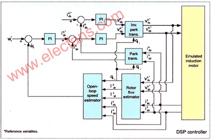
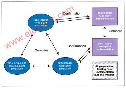
If you use an ADC with double sample and hold circuits, you can avoid this error. The numerical representation of the algorithm is the most critical area where quantification effects exist. Simultaneous use of simulation and experimental analysis methods to study actual digital controllers is a practical method for analyzing quantization errors. The system shown in Figure 1 below uses simulation execution and test execution.

Figure 1: The choice of digital processor is a major issue to consider when implementing a digital motor control system
The algorithm of the system adopts three formats: 16-bit fixed-point, 32-bit fixed-point and 32-bit IEEE-754 single precision, all using the same 32-bit fixed-point digital controller-TMS320F2812 of TI Company, and for 32-bit fixed-point programming TI's "IQmath" library.
The "IQmath" library allows designers to easily and quickly convert C code written in floating-point format to 32-bit fixed-point format. Because the efficiency of performing floating-point calculations on fixed-point processors is not high enough, the implementation of floating-point formats requires a longer sampling time of 4kH. Therefore, to be fair, the experimental results will only be compared between 16-bit and 32-bit fixed-point formats.
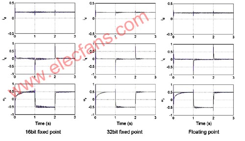
In order to compare the effects of the three data formats on numerical accuracy, the estimated speed response and the corresponding d-axis and q-axis reference currents were observed.

Figure 2: Simultaneous use of analog and experimental analysis methods to study actual digital controllers is a practical method for analyzing quantization errors
The 16-bit fixed-point system (Figure 2 above) exhibits pseudo transients and ringing, while the 32-bit does not. The results of the experiment also showed similar characteristics. In actual systems, these transient phenomena will bring audible noise and vibration (see Figure 3 below).
Sampling frequency A key factor that any digital system must consider is the sampling frequency-Nyquist theorem. The highest frequency component in the system must be derived. It is common practice to select at least 4 times the frequency for the first-order system. To demonstrate this effect, we decompose a simple unipolar transfer function. The transfer function is expressed by the formula: G (s) = s + 100/100 In the proper sampling interval, the coefficients are no problem. But when oversampling, serious resolution problems will occur. Check the coefficient size, you can find the quantization effect. As the sampling rate increases, the numerator coefficient will decrease.
When the sampling rate is 10 microseconds, the coefficient drops to 0.00999950016, which is displayed as 0x0020. This means that the coefficient has a 5-bit resolution, which is a serious problem for 16-bit processors. At this time, if you use 32-bit operation, you can get a better value. In this case, a 32-bit processor that can express fractions with native 32-bits, such as the TMS320F2812, can avoid these problems.
Generate PWM output The digital pulse width modulator (PWM) in the embedded controller uses a counter and a compare buffer to generate the PWM output. But this kind of scheme has its shortcomings: The smallest change in the PWM output is equal to the clock period of the counter, which will cause quantization problems when the PWM frequency increases.
This is especially important when controlling the power factor correction phase associated with motor-controlled inverters. In this case, PWM frequencies in excess of 200 kHz are common. At this time, the PWM resolution of the 100MHz component is about 8 to 9 bits, which will cause the problem of limit cycle. The high-resolution PWM architecture implemented for the first time by the TMS320F280x digital signal controller can solve this problem. This architecture can provide a resolution of 150 ps.

Figure 3: The system is implemented in simulation and actual implementation, and the algorithm is implemented in three different formats: 16-bit fixed-point, 32-bit fixed-point, and 32-bit IEEE-754 single precision floating point

Figure 4: Pseudo-transient and ringing occurs in 16-bit fixed-point systems, but not in 32-bit
Figure 4 above shows the high-resolution PWM and standard PWM in operation. It can be seen from the software curve that a ladder will occur when the high-resolution function is turned off.
When the high-resolution function is turned on, a yellow curve is formed. Obviously, high-resolution PWM can reduce the quantization error in the PWM output by several orders of magnitude, thus significantly reducing the limit cycle caused by lower-resolution PWM.
System designers can use 32-bit operations to improve the performance of motor control systems. Moreover, the 32-bit operation eliminates the need for designers to examine the algorithm's quantization issues in detail, allowing them to use higher sampling rates, thereby increasing system bandwidth. In order to fully understand the quantization effect and get the best performance, designers must properly solve the problem of output quantization through technical improvements such as high-resolution PWM.
HIGH QUALITY:Made of only the highest quality materials and built to last! Our chargers are gauranteed to match the original brand name chargers' quality.
EASY TO USE: Simply plug the charger into a wall outlet and then directly into your scooter.
The charger protected: Short circuit protection/ over current protection/ over voltage protection; red light -- charging, green light -- charge OK, it stop automatically when the battery is full. Warm Tips: To avoid the temperature of your charger too high, please do not charge too long.
The shell is made by high-quality plastic, smooth appearance with no impurities. Good safety performance, more reliable for you to use. Red light means charging; Green light means fully charged or disconnect.Aviation Plug Scooter Charger,Power Scooter Charger,Li-Ion Battery Charger
Shenzhen Waweis Technology Co., Ltd. , https://www.waweispowerasdapter.com