Noise reduction is an important design issue in most electronic systems. As with power consumption limits, ambient temperature variations, size limits, and speed and accuracy requirements, ubiquitous noise factors must be addressed to make the final design a success.
Here, we do not consider the technique used to reduce "external noise" (together with the signal) because its presence is generally not directly controlled by the design engineer. In contrast, it is the direct responsibility of the design engineer to prevent "internal noise" (noise generated or coupled within the circuit or system) from disturbing the signal. Today we will talk about "grounding" and it is "grounding" for high frequency operation.
"Grounding" generally refers to the connection of a circuit, device, or system to a good conductor that acts as a reference or reference potential plane, creating a low impedance path between the circuit or system and the ground.
The ground line is an equipotential body that serves as a reference point for the circuit or system potential. It is the common conductor of each circuit in the system. The current of any circuit will form a loop through the ground. However, any conductor has a certain impedance. When there is current in the local line, according to Ohm's law, there will be voltage on the ground, then the ground is not an equipotential body. Therefore, in the actual design of the circuit or system, the assumption that the potentials at the points on the ground line must be equal is not true. The actual situation is that there is a potential difference at each point on the bottom line, and some phase differences may be large. The common impedance of the ground wire creates a certain voltage between the grounding points, which causes grounding interference.
As mentioned above, the ground wire acts as a conductor, and there is a certain impedance. As the name implies, the impedance is composed of two parts: resistance and inductive reactance, namely:
The impedance of a conductor is a function of frequency, and as the frequency increases, the impedance increases rapidly. For high-speed digital circuits, the clock frequency of the circuit is very high. The pulse signal contains a high frequency component, so a large voltage is generated on the ground line, and the ground line impedance is very disturbing to the digital circuit.
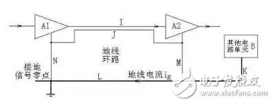
In the PCB design of electronic products, suppressing or preventing ground interference is one of the most important issues to consider. The so-called interference must occur between different unit circuits, components or systems, and the ground interference refers to the signal interference generated by the common ground. Note that the signals mentioned here usually refer to AC signals or hopping signals. There are many forms of ground interference. Some people attribute it to two types: ground loop interference and common impedance interference. In fact, electromagnetic coupling interference of the ground loop should be added, so it is of three types. The figure below is a good illustration of the causes of the three types of ground interference.

First, the ground loop interference. Lateral, the current on each wire is different, so differential mode voltage is generated, which affects the circuit. Specifically, the ground current of "other circuit unit B" affects amplifiers A1 and A2 in the "ground loop" formed by J, N, L, and M. Since this interference is caused by the loop current composed of the cable and the ground, it becomes a ground loop interference.
Second, the ground loop electromagnetic coupling interference. On the PCB of the actual circuit, the "ground loop" formed by J, N, L, M will surround a certain area. According to the law of electromagnetic induction, if there is a changing magnetic field in the area surrounded by this loop, An induced current is generated in the loop to form an interference. The change of the spatial magnetic field is ubiquitous, so the larger the area enclosed, the more serious the interference.
Third, the common impedance interference. Careful examination of the circuit structure shown in the above figure, we will find that one of J, N, L, M is redundant, just remove one, still can meet the connection relationship of each ground point, and at the same time eliminate the ground Line loop. So, which one is more reasonable to remove? At this time, another type of interference problem should be considered - common impedance interference.
1 Remove J: This is the worst solution. After J is removed, the ground loop seems to disappear, but another more terrible loop is formed (I, N, L, M), where I is the signal line, so the interference is more serious than the original cable J.
2Remove M: The loop disappears, but we find that the ground current of amplifier A2 needs to flow through J and N to reach the ground zero. Note that the N segment is the common ground wire of A1 and A2, so the ground current of A2 is formed on N. The voltage drop is added to A1, creating interference. This interference caused by sharing a ground line is called "common impedance interference."
3 Removal of L: Not only can not solve the common impedance interference problem between A2 and A1, but also cause the common impedance interference problem between "B unit circuit" and A1, A2.
4 Remove N: It seems that this is the last method. In fact, doing so will make M become the "common impedance" of A1 and A2, and also form interference. Still have problems! However, we noticed that the interference in this method is the interference of A1 to A2, A2 is the latter stage, and the working signal strength is much larger than A1. Therefore, the interference of A1 on A2 is difficult to cause adverse consequences.
The most reasonable routing scheme is to remove N and then connect the lower end of M directly to the "ground signal zero".
The above is about the cause of grounding interference. The following several common grounding methods, combined with the previous understanding of the cause of grounding interference, help us to correctly select the grounding with the least interference when actually designing the PCB board circuit. Ways to design a reasonable circuit or system.
Signal grounding methods can be broadly divided into: single-point grounding, multi-point grounding, hybrid grounding, and floating grounding.
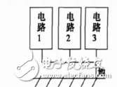
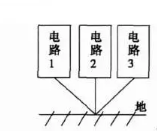
First, a single point of grounding. Single point grounding is to use a point in the real circuit system as the grounding reference point. All the ground lines of the circuit and equipment must be connected to this point, and use this point as the zero potential reference point of the circuit and equipment. Single-point grounding is divided into series single-point grounding and parallel single-point grounding. As shown below:

Figure 2. Series single point grounding
For the series single-point grounding method, if the power of the circuit is large, a large circuit reflow will occur, and a voltage drop will occur at the finite impedance, causing a difference in the voltage reference between the circuit and the reference ground to make the system Can't work as expected. If there are multiple circuits of different power levels, the series single-point grounding method cannot be used because the high-power circuit generates a large return current, which will affect the low-power devices and circuits. If this grounding method must be used, the most sensitive circuit must be placed directly at the power input location and as far away as possible from low power devices and circuits. The series single-point grounding method and structure are relatively simple. If the grounding leads of each circuit are relatively short, the impedance will be relatively small. This grounding method can be used if the grounding level of each circuit does not differ much.

In the parallel single-point grounding mode, each circuit unit is connected to the agreed location by a separate ground wire. The advantage is that the location of each circuit is only related to the ground current and ground impedance of the circuit, and is not affected by other circuits. Low-impedance interference between circuit units can be effectively avoided at low frequencies, but there are also many disadvantages. The main performances are as follows: First, each circuit is grounded by an independent ground wire, which requires more ground wire, which will increase the length of the ground wire, thereby increasing the ground impedance, and the complicated structure is troublesome. Secondly, this grounding method will cause the lines to be mutually Coupling, and as the frequency increases, the ground impedance, ground inductance, and wire capacitance increase. This grounding method is not suitable for high frequency circuits.
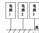
Second, multi-point grounding. Multi-point grounding means that each circuit and equipment in a system that needs to be grounded is directly connected to the ground plane closest to it. The grounding length is the shortest and the grounding impedance is minimized.

When the operating frequency of the electronic system is higher than 1 MHz, so that the working wavelength is comparable to the length of the system ground lead, the ground line is like a transmission line with a terminal short circuit, the current and voltage of the ground line are standing wave distribution, and the ground line becomes The antenna is radiated, and it cannot function as a ground. In order to reduce the grounding impedance and avoid radiation, the length of the ground wire should be less than 1/20 wavelength. Therefore, the single-point grounding method is unreasonable, and multi-point grounding technology is usually adopted. The multi-point grounding circuit has a simple structure, and the high-frequency standing wave phenomenon that may occur on the grounding wire is significantly reduced, but multi-point grounding may cause many grounding loops to be formed inside the device, which is easy to cause ground loop interference in sensitive stores inside the device.
APM programmable AC Power Supply can be remote controlled and integrated with other systems for easier operation. Applications include home appliance, lighting,electronic, medical equipment, and etc.The adjustable ac power supply gives you just the right performance at just the right price.
This AC source model SP300VAC1000W adopts high speed DSP+CPLD control, high frequency PWM power technology and active PFC design to realize AC/DC stable output.
Some features as below:
- 4.3"large touch color screen
- AC+DC mixed or independent output mode
- Capable of setting output slope/phase angle
- Built-in IEC standard test function
- Built-in multiple protections
- Built-in power meter
- Support impedance function
- Support for LIST/PULSE/STEP mode & Transient mode
- Standard RS232/RS485/USB, Optional GPIB//LAN
- Support harmonics/inter-harmonics simulation and measuring function
- Support for USB data import/export and scree nap from front panel
1000W AC Power Supply,AC Switching Power Supply,Ac Bench Power Supply,1000W Ac Dc Power Supply
APM Technologies Ltd , https://www.apmpowersupply.com