Introduction This application note outlines the loopback function of the Dallas Semiconductor T1 / E1 / J1 transceiver. T1 and E1 are terms used to describe 1.544Mbps and 2.048Mbps transmission over any medium.
Loopback mode is useful for diagnostic testing of devices or equipment. In the loopback mode, the transceiver sends the signal transmitted through the network or a specific link from one end of the transceiver back to the other end of the sending device. Compare the signals from both ends. The difference between the two helps to track down the fault.
Loopback Dallas Semiconductor T1 / E1 / J1 transceiver supports six types of loopback. Remote Loopback (RLB) Local Loopback (LLB) Framer Loopback (FLB) Diagnostic Loopback (DLB) Payload Loopback (PLB) Per Channel Loopback (PCLB) Remote Loopback (RLB) Loopback facilitates users to test the far end of the device link. In the remote device, the signal passes through the LIU and jitter attenuator. When the RLB bit of the control register is set to low, remote loopback is disabled. When the RLB bit of the control register is set to low, remote loopback is disabled.
When the RLB bit of the control register is set to high, remote loopback is enabled.
In far-end loopback, the data input through RTIP and RRING is sent back to TTIP and TRING after passing through the jitter attenuator. The data passes through the framer at the receiving end of the device as usual. Data from the formatter at the sending end is ignored.
See Figure 1 for details.
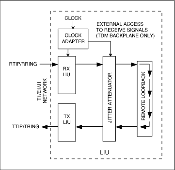
Figure 1. Typical remote loopback mode of operation
When the LLB bit of the control register is set to low, local loopback is disabled.
When the LLB bit of the control register is set to high, local loopback is enabled.
In local loopback, the transmitted data is transmitted through the transmitting part of the transceiver as usual. The data received on RTIP and RRING is replaced by the sent data. The local loopback data passes through the jitter attenuator.
See Figure 2 for details.
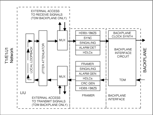
Figure 2. Typical local loopback mode of operation
When the FLB bit of the control register is set to low, the framer loopback is disabled.
When the FLB bit of the control register is set high, the framer loopback is enabled.
When framer loopback is enabled, the signal from TSER returns to RSER through the framer. This type of loopback is used to verify the function of the framer. In the framer loopback in T1 mode, unframed all 1 codes are sent from TPOSO and TNEGO. In E1 mode, standard data is sent from TPOSO and TNEGO.
In framer loopback mode, all receiver signals are synchronized with TCLK instead of RCLK. When using framer loopback, RCLK cannot be connected to TCLK during this loopback, as this will cause a non-operational state.
See Figure 3 for details.
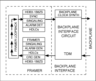
Figure 3. Typical framer loopback mode of operation
The diagnostic loopback sends the data packet back to the receiving end of the Utopia bus. This mode is suitable for telecommunications devices such as DS2156, DS26101 or DS26102 of Dallas Semiconductor.
In the diagnostic mode, the data, clock, and frame pulse indications generated by the SCT transmission section replace the corresponding signals from the physical layer devices. The physical receive interface mode should be configured to the same value as the physical transmit interface mode. The receive valid edge selection bit should be configured as the opposite edge of the same SCT transmit section.
The details are shown in Figure 4.
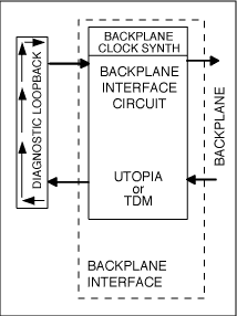
Figure 4. Typical diagnostic loopback mode of operation
When the PLB bit of the control register is set to low, the payload loopback is disabled.
When the PLB bit of the control register is set high, payload loopback is enabled.
When payload loopback is enabled, the signal from RTIP / RRING is sent back to TTIP / TRING through LIU and the framer. In this type of loopback mode, the transmitted data is synchronized with RCLK instead of TCLK. All receiver signals work as usual. The data of TSER, TDATA and TSIG pins are ignored.
In T1 mode, payload loopback can be performed in D4 and ESF framing modes. When PLB is enabled, SCT sends 192-bit payload data (corrected by BPV) from the receiving end to the sending end. FPS frame mode, CRC6 check code and FDL bit do not participate in the loopback, they are reinserted by SCT.
In E1 mode, the payload loopback sends 248 bits of payload data (corrected by BPV) from the receiving end to the sending end. The sender adjusts the payload as if it was entered by TSER. FAS words, Si, Sa, and E bits, and CRC4 do not participate in the loopback. They are reinserted by SCT.
The details are shown in Figure 5.
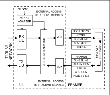
Figure 5. Typical payload loopback mode of operation
Each bit in the channel loopback register (PCLR1 / PCLR2 / PCLR3 / PCLR4) represents a DS0 channel in the output frame. When these bits are set to 1, the data from the corresponding receive channel will replace the data on the channel TSER.
- The Description of wifi Antenna
-
When selecting the antenna, it is necessary to pay attention to whether the connector of the antenna matches the connector of the connected device. Generally, SMA and TNC are used for WIFI
To use on the router, but on the 2.4 G wireless monitoring equipment fittings, if match, also can achieve the enhancement effect of the wireless signal transmission Magnetic antenna base, can suck on metal surfaces, makes the antenna signal is stronger Plug and play, without any additional conditions, but the antenna gain and directional property management are key points to consider. - The first standard WIFI antenna products were made by LTCC process, because of its width and general performance. Abroad, Airgain has launched a standard antenna with high temperature resistance and plastic seal, which is used in laptop computers, and a series of WiFi antennas with magnetic dielectric in mobile phones have been launched in China.
- The Picture of wifi Antenna
-
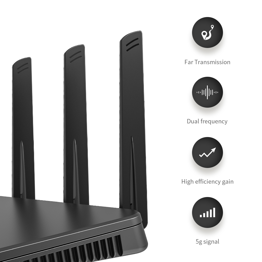
Wifi Internal Antenna,Wifi Antenna for PC,Wifi Antenna for Router,Wfi Antenna outdoor,Wifi Antenna Indoor
Yetnorson Antenna Co., Ltd. , https://www.yetnorson.com