1 Instrument basic principle
The LED photoelectric parameter tester is composed of two parts, light and electricity, and mainly includes sensors, input circuits, A/D conversion circuits and digital display circuits. The photoelectric receiver as the instrument sensor is a key component of the instrument measurement. It is matched by optoelectronic devices (such as selenium photocells) and appropriate filters, and undergoes strict V ( λ ) correction to make its spectral sensitivity. The curve is consistent with the standard visual function V ( λ ) curve throughout the visible region. In addition, a constant length of the light-shielding cylinder is arranged at the front of the photoelectric receiver to determine the viewing angle and the measuring distance of the receiver, and the cylinder is provided with a plurality of apertures for eliminating external stray radiation.
2 Overview of calibration methods
There are generally two methods for calibrating the normal illuminance of the instrument: one is to calibrate with an LED tube of known illuminance value; the other is to calibrate using a standard lamp of constant color temperature and known illuminance value. The first method is simple and convenient to operate, but the measured value is single, and the standard sample tube is not stable enough. The second method is carried out on a photometric measuring device, which can continuously calibrate in multiple steps, and the standard lamp is stable in illumination, so the measurement accuracy is relatively high. In this paper, the measurement uncertainty of the normal luminescence intensity of the instrument is measured under the second calibration method.
Now let's take a closer look at the second calibration method. Assume that a standard light with a color temperature of 2856K is selected. The luminous intensity is known as I0. The distance between the standard lamp and the receiver of the instrument is R. At this time, the illumination produced by the standard lamp on the surface of the instrument detector E, E = I0 / R2, this illuminance value is equivalent to the standard light intensity source from the photodetector r (the length of the receiver light-shielding cylinder) and the luminous intensity Ix. So Ix = E·r2 = I0·r2 /R2. This indicates that the instrument indication value Ix is proportional to the standard lamp luminous intensity value I0 and the square of the length of the light-shielding cylinder, and inversely proportional to the square of the distance between the standard lamp and the instrument detector surface. It can be seen that the calibration principle of this instrument is similar to that of the illuminometer. The calibration can also be performed on the illuminance measurement standard device. As long as the standard lamp or detector is moved on the track, the standard lamp is changed to the surface of the instrument detector. The distance of the instrument can be measured by different luminous intensity values ​​of the instrument, thereby realizing the calibration of the luminous intensity of the instrument. It must be noted here that the distance between the standard lamp filament plane and the instrument detector surface during calibration should be at least 15 times greater than the maximum line of the illuminant or receiving surface. In addition, the premise of the calibration of the normal illuminance intensity of the instrument by this method is that the photoelectric receiver of the instrument should undergo a strict V ( λ ) correction so that its spectral sensitivity curve and the standard visual function V ( λ ) curve are The entire visible light area is consistent.
3 Measurement uncertainty assessment
3. 1 assessment model
3. 1. 1 Mathematical formula

Where I—the luminous intensity value measured by the instrument, in cd.
I0———The luminous intensity of known standard lamps, in cd.
R ———The distance from the filament plane of the standard lamp to the surface of the instrument detector, in m.
r———The distance from the LED to the detector surface (the length of the receiver light-shielding tube) in the instrument design, in m.
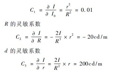
3. 1. 2 sensitivity coefficient
For an LED light intensity tester that meets the requirements of the CIE specification, r is a certain value, that is, in the CIE condition A, r = 0.316 m, and in the CIE condition B, r is 0. 100 m [1]. Select a standard lamp, the known light intensity I = 1000cd, and the surface of the instrument detector R = 1m, calculate the theoretical value of the normal luminous intensity of the instrument I = 10 cd (this is taken as an example in the following calculations).
Then: the sensitivity coefficient of I0

3. 2 Analysis of uncertainty sources
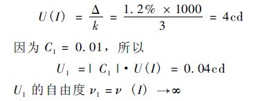
3. 2. 1 Uncertainty component U1 caused by the standard uncertainty of the light intensity of the standard lamp U(I0) (Class B)
3. 2. 2 Uncertainty component U2 due to the standard uncertainty U ( R) of the distance measurement from the filament plane of the standard lamp to the surface of the instrument detector. U2 is the synthetic uncertainty and consists of the following uncertainty components.
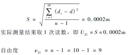
â—† Uncertain component U21 caused by repeatability measurement (Class A rating)
â—† Uncertain component U22 caused by measurement error of light rail (Class B assessment)
3. 2. 3 The error standard of the length measurement of the receiver light-shielding cylinder is uncertain
Degree of uncertainty U(r) caused by the uncertainty component U3 (Class B assessment). It is particularly important to point out here that during the calibration process, the power supply and electrical measurement equipment required for the working environment and standard lamps shall meet the requirements set forth in the illuminance measurement standard device.
3. 3 Evaluation of uncertainty components
3. 3. 1 U1 assessment
The uncertainty of the standard lamp is given by the illuminance standard device magnitude transfer diagram: Δ = 1. 2%, k = 3. Therefore, the above information is very reliable, so the degree of freedom of U ( I) ν( I) →∞

3. 3. 2 U2 assessment
3. 3. 2. 1 Assessment of U21
In order to obtain the uncertainty of the repeatability measurement, the distance between the standard lamp and the instrument detector is measured, and the measurement is repeated 10 times. The measured data is as follows (unit: m): 1. 0002, 1. 0000, 1. 0003, 1. 0002, 1. 0000,0. 9998,0. 9998,1. 0002,1. 0003,1. 0000. The standard deviation S of a single measurement is
