I. Project Overview
1.1 Introduction
The motor is an indispensable power equipment for industrial production. There are many varieties of motors and their functions are quite extensive. A new type of traction motor for linear switched reluctance motors. It has the following main advantages: the structure is simple, and the production cost is not high. The work is stable and can work normally in a harsh environment for a long time. For example, in a high temperature environment, the switched reluctance motor has better heat dissipation performance and can work normally at high temperatures. With the development of power electronics technology, switched reluctance motor control will become easier and control effect will be better. The motor has large starting torque, strong overload capability and wide speed regulation range. In addition to the above advantages, linear switched reluctance motors have shown great advantages in some situations where linear motion is required: no longer need to be driven by a screw or the like like a conventional linear motion device. The motion of the rotation is converted into a linear motion. This once again saves the intermediate link, which not only reduces the cost of the equipment, but also improves the energy utilization rate. Switched reluctance motors have high control precision and have broad application prospects in high-precision machining and high-power transmission.
1.2 Project Background / Motivation
There are many high-precision machining platforms that require linear traction mechanisms. Most of the current processing platforms use traction motors for traction, and then use mechanical transmissions to convert motion into linear motion. This will not only cost equipment but also be inefficient. The linear switched reluctance motor itself is in the form of a straight line. If it is applied to these devices, the cost of the device will be greatly reduced and the efficiency will be improved.
Second, the demand analysis
This design is roughly divided into four parts:
(1) The design of the overall system plan, including system function analysis, system architecture establishment, system hardware design and other processes.
(2) Based on the application of MCU A/D, D/A, PWM and other resources.
(3) Design of the motor module.
2.1 Functional requirements
(1) Current sensor
The sensor is responsible for collecting the linear motor current for feedback to the controller for processing.
(2) Position encoder
The position encoder feeds back the position of the motor's motion to the controller for processing.
(3) Microcontroller
The microcontroller is responsible for processing the current collected by the sensor and the position returned by the encoder. When the position command is given, the motor moves to the specified position accurately and quickly.
(4) Keyboard module
The keyboard module is responsible for the given input.
The linear switch reluctance motor position control system architecture is shown in Figure 1.
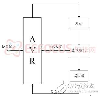
Figure 1 system architecture diagram
2.2 Performance requirements
(1) Stability
The system can work stably and has good anti-interference ability.
(2) rapidity and real-time
The motor can move quickly to the specified position for real-time control.
(3) Accuracy
The motor can move to the specified position accurately.
Industrial Main Board Cable:SCSI,D-SUB,DVI,Wire to Wire ,RJ45...
There are five types of main board power line interface, and different external devices correspond to different interfaces. Different interfaces and their connecting pins are also different. For example, the pin of the main power supply is 24 pins, and the hard disk drive is 5 pins.
1. 20pin + 4Pin interface: it is a common interface combination, in which 20pin is the main power interface and 4Pin is the auxiliary power supply interface.
2. 5pinsata interface: special interface for power supply of hard disk and optical drive.
3. 6pin? PCI? Express connector: a special interface for independent graphics power supply.
4. 4Pin connector: it is a kind of floppy disk power connector, which is used to power the floppy drive equipment.
5. 4Pin power interface: optical drive, old IDE hard disk and peripheral hardware power supply interface.
Industrial Main Board Cable
ShenZhen Antenk Electronics Co,Ltd , http://www.coincellholder.com