[Introduction] Closed-loop regulated pulse width modulation (PWM) inverter power supplies are widely used in various types of AC power supply systems, such as: uninterruptible power supply (UPS), voltage regulator (AVR), programmable AC power supply. (PAS), etc.
Closed-loop regulated pulse width modulation (PWM) inverters are widely used in various types of AC power systems, such as uninterruptible power supplies (UPS), voltage regulators (AVR), and programmable AC power supplies (PAS). Wait. In these systems, it is required to output a waveform with a low harmonic content under transient or periodic load variations. Many research schemes use instantaneous feedback control techniques, such as instantaneous voltage and current tracking, deadbeat control, and state feedback control, to obtain better dynamic response. However, this type of method can only make the system have better adjustment ability for instantaneous load changes, and the periodic harmonic suppression ability caused by periodic load changes is very poor. Therefore, for systems with non-linear loads, such as rectifying loads, the total harmonic content of the output is still high. In addition, the above several methods of instantaneous feedback control still have shortcomings from the principle of self-control, and hinder their further promotion and application. Among them, the instantaneous voltage and current tracking method, so-called two-state (or three-state) hysteresis control (Delta-PWM), the switching frequency of the circuit is higher, and the accuracy is improved, and the switching frequency follows the output. The amplitude changes and the harmonic components are randomly distributed. The analysis of the output spectrum is difficult and is not conducive to the design of the output filter. The design of state feedback control is based on the accurate mathematical model of the system, and requires state feedback gain to optimize the design to increase the robustness of the system, and the error of these two aspects can be very large, thus reducing the performance of the system. As for the deadbeat control, since the principle is based on the circuit calculation method, it is very sensitive to changes in component parameters in the circuit, which is less applicable to applications where the load is constantly changing. Although some literatures have proposed improved solutions, such as adding a load parameter identifier, the effect is still not satisfactory.
The performance of the PWM inverter power supply ultimately depends on the quality of the control strategy. As a modern control method, adaptive control is suitable for the case where the mathematical model of the system is unknown or changes during operation. This provides a solution to solve the problem of waveform distortion caused by load changes in the inverter. The author is conducting an in-depth study on this kind of adaptive inverter power based on the hardware of DSP and MCU 196. It can automatically eliminate the AC cycle distortion caused by the unknown load periodic disturbance and greatly improve the quality of the power supply.
2 working principle 
Referring to Fig. 1, in this system, the whole of the inverter bridge, the LC filter, and the rectifying RC load are controlled by the system. Among them, Ud
Design and Implementation of an Adaptive Inverter
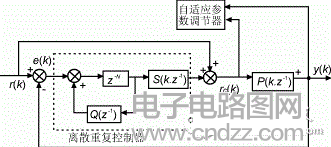
Figure 1 The structure of the adaptive PWM inverter power supply is DC power supply voltage, g1, g2, g3, g4 are power tube switching signals, U1, U2 are current and voltage feedback signals respectively. This adaptive control scheme is represented by Figure 2.
Where: r(k) - reference signal;
y(k)—system output;
e(k) - error signal;
Q(z-1), S(k, z-1) - auxiliary compensator;
Rc(k) - the compensated reference signal;
P(k, z-1)—The closed-loop transfer function of the system controlled object.
The control system mainly includes two parts: one is a discrete repeating controller and the other is an adaptive parameter regulator. They work as follows:
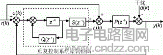
(1) Discrete Repetitive Controller Repeat control refers to a control scheme that eliminates all periodic errors contained in a stable closed loop, as shown in Figure 3.
Where P(z-1) represents the transmission of the controlled object, d(k) is the * signal, and the rest of the signals are defined as in Figure 2.
Available from the map: ![]()
E(z-1) and D(z-1) are the Z transform of e(k), d(k). If d(k) is a perturbation with a period of N, then the Fourier transform is ![]()
|Cn| represents the Fourier coefficient and the transfer function can be expressed in the frequency domain as if Q(z-1)=1 and P(z-1) is stable, then
|H(jω)|=0(ω=2nπ/N, n=0,...,N-1)
This shows that these periodic errors can be eliminated by the repeat controller, in which case error-free following can be obtained. However, this requires a strong degree of stability. In practical applications, this condition can be weakened, such as:
|H(jω)|"μ (jω ) ( ω=“2nπ†/N, n=“0,†.., N- 1)
Here μ(jω) is the allowable range of the periodic error.
(2) The adaptive parameter adjuster adds an adaptive parameter adjuster based on the repeated control system to form an adaptive repeat control system. The adaptive parameter adjuster is essentially an algorithm that makes the system adaptive and can adjust the control parameters according to the actual system characteristics to achieve the desired performance indicators. In this system, the adaptive parameter adjuster uses the recursive least squares algorithm (RLSE) to identify the structural parameters of the controlled object of the system in real time, thereby adjusting the parameters of the discrete repeat controller according to the desired performance index.
As shown in Fig. 2, in the present control scheme, a closed loop of the signal U1, U2 in FIG. 1 is first constructed, and the closed-loop transmission is denoted as P(z-1), and is considered to be a second-order time-varying structure. , which is ![]()

Fig. 2 Adaptive repetitive control system control block diagram type a1, a2 is a time-varying parameter, the control idea is: firstly, the adaptive parameter adjuster online identifies the structural parameters a1(k), a2(k) of the controlled object of the system Then, the parameters of the auxiliary compensator S(k, z-1) are adjusted according to the identification result to obtain a control law adapted to the system structure, so that y(k) follows r(k). Since the identification is real-time, the system can always be controlled according to the actual operating conditions, so that the precision of the control can be improved, which realizes the idea of ​​self-adaptation. 
Figure 3 repeat control system block diagram
3 Experiments and effects According to the literature [6], the scheme has been realized in 2kVA, output 100VAC, 60Hz inverter and achieved good results.
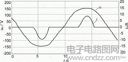
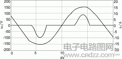
(1) For a rectifying load with a peak factor of 3, state feedback control is used under the same conditions, and the output voltage THD value is 8%, and the THD value can be reduced to 1% within 0.2 s after adaptive control [6]. The output waveform comparison under the two schemes is shown in Figure 4.
(2) This scheme effectively eliminates the impact on the system output due to periodic unknown system characteristic parameter changes (including load parameters, component parameters). 

Figure 4 Output waveforms of two control schemes (a) State feedback control scheme (b) Adaptive control scheme (3) Compared with other control schemes, this scheme not only has a faster error convergence speed, but also ensures that the system is Stability under large load disturbances (4) Compared with the load parameter identification applied in the deadbeat control method, the scheme identifies the structural parameters of the system.
It is a general consideration, not just a partial focus, so it is more advanced and more conducive to application.
(5) The solution is more advantageous in that it is not necessary to know the exact mathematical model of the PWM inverter power system at the time of design, but only need to replace it with the real-time identification model in the application. This provides a way for the adaptive control method to be directly applied to the traditional analog-controlled PWM inverter power supply, thereby effectively improving the quality of its output.
In general, the adaptive control method of the PWM inverter power supply described in this paper has its unique advantages, is a novel method, and solves some practical problems. Of course, as a new type of control method, it certainly has a lot to be perfected. Since adaptive control is a nonlinear control scheme after all, its design is naturally more complicated than conventional feedback control, and system modeling and stability analysis are also very difficult. The author is doing further research work to make it practical as soon as possible.
men's quartz field watch,stainless steel men's quartz watch,quartz movement watch,quartz watch water resistant
Dongguan Yingxin Technology Co., Ltd. , https://www.dgyingxintech.com