Programmable controller, called Programmable Controller in English, referred to as PC. However, since PCs are easily confused with personal computers, people are still accustomed to using PLCs as abbreviations for programmable controllers. It is a microprocessor-based digital computing operation electronic system device designed for industrial field applications. It uses programmable memory to perform logic operations, sequence control, timing/in its internal memory. Operational instructions such as counting and arithmetic operations, and control various types of mechanical or production processes through digital or analog input and output interfaces. PLC is a combination of microcomputer technology and traditional relay contact control technology. It overcomes the shortcomings of complicated wiring, low reliability, high power consumption, versatility and poor flexibility of mechanical contacts in relay contact control systems. Make full use of the advantages of the microprocessor, and take care of the skills and habits of the on-site electrical operation and maintenance personnel, especially the programming of the PLC, without the need for specialized computer programming language knowledge, but based on a relay ladder diagram The simple instruction form makes the user program image, intuitive, convenient and easy to learn; debugging and error checking are also very convenient. After purchasing the required PLC, the user can simply and flexibly and conveniently apply the PLC to the production practice by simply making a small amount of wiring and simple user programming according to the instructions of the manual.
First, the structure of the PLC and the role of each partThere are many types of PLCs, functions and command systems are different, but the structure and working principle are similar. Usually, it consists of several main parts: host, input/output interface, power expander interface and external device interface. The hardware system structure of the PLC is shown below:
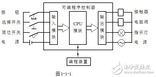
Figure 1-1-1
1, the host
The host portion includes a central processing unit (CPU), system program memory, and user programs and data storage. The CPU is the core of the PLC. It is used to run the user program, monitor the status of the input/output interface, make logical judgments and perform data processing, that is, read the input variables, complete various operations specified by the user instructions, and send the results to the output. And respond to requests from external devices (such as computers, printers, etc.) and make various internal judgments. There are two types of PLC internal memory, one is system program memory, which mainly stores system management and monitoring programs and programs for compiling and processing user programs. The system programs are fixed by the manufacturer and cannot be changed by users; the other is user programs and Data storage, mainly for user-programmed applications and various temporary data and intermediate results.
2, input / output (I / O) interface
The I/O interface is the part of the PLC that is connected to the input/output device. The input interface accepts control signals from input devices such as buttons, sensors, contacts, travel switches, and the like. The output interface is to drive the output device (such as contactor, solenoid valve, indicator light, etc.) through the power amplifier circuit after processing the host. I/O interfaces generally use optocoupler circuits to reduce electromagnetic interference and improve reliability. The number of I/O points, that is, the number of input/output terminals, is a major technical indicator of PLC. Usually, there are dozens of points in a small machine, hundreds of points in a medium machine, and more than a thousand points in a mainframe.
3, the power supply
In the figure, the power supply refers to a DC switching power supply configured for internal electronic circuits such as CPU, memory, I/O interface, etc., and usually supplies DC power to the input device.
4, programming
Programming is the use of external devices by the PLC to input, check, modify, debug, or monitor the operation of the PLC. Connect the PLC to the computer via a dedicated PC/PPI cable and use dedicated software for computer programming and monitoring.
5, input / output expansion unit
The I/O expansion interface is used to connect an expansion unit that expands the number of external input/output terminals to a base unit (ie, a host).
6, external device interface
This interface can connect external devices such as printers, barcode scanners, and inverters to the host to complete the corresponding operations.
The host model provided by the experimental device is CPU224 (AC/DC/RELAY) of Siemens S7-200 series. The number of input points is 14, the number of output points is 10; CPU226 (AC/DC/RELAY), the number of input points is 26, and the number of output points is 14.
Second, the working principle of PLCThe PLC works by means of "sequential scanning, continuous cycling". That is, when the PLC is running, the CPU prepares a program that is stored in the user memory according to the control requirements, and performs periodic cyclic scanning according to the instruction step number (or address number). If there is no jump instruction, the first instruction starts. The user program is executed sequentially one by one until the end of the program. Then return to the first instruction and start the next round of new scans. During each scan, the sampling of the input signal and the refresh of the output state are completed.
One scan cycle of the PLC must pass the three stages of input sampling, program execution and output refresh.
During the input sampling phase of the PLC: firstly, the on-off state or input data of all the input terminals temporarily stored in the input latch are read in order by scanning, and written into each corresponding input status register, that is, the input is refreshed. . The input port is then closed and the program execution phase is entered.
In the program execution phase of the PLC: each instruction is scanned and executed according to the order in which the user program instructions are stored. After the corresponding operation and processing, the result is written into the output status register, and all contents in the output status register are executed along with the program. And change.
Output refresh phase: When all instructions are executed, the on/off state of the output status register is sent to the output latch during the output refresh phase, and is output through a certain mode (relay, transistor or thyristor) to drive the corresponding output device to work.
Third, PLC programmingProgramming component
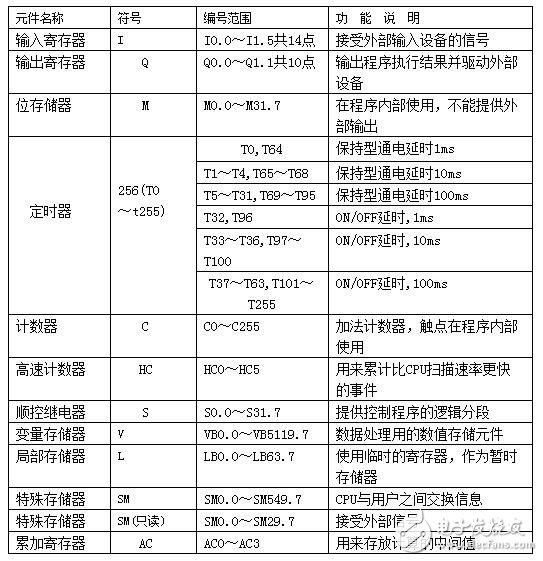
PLC uses software programming to achieve control requirements. A variety of programming components are used for programming, which provide numerous moving and breaking contacts. Programming elements are input registers, output registers, bit memories, timers, counters, general purpose registers, data registers, and special function memories.
The functions of these memories inside the PLC are very similar to those used in relay contact control systems. There are also "coils" and "contacts", but they are not "hard" relays, but rather storage units for PLC memories. When the logic state written to the unit is "1", it means that the corresponding relay coil is energized, its moving contact is closed, and the breaking contact is open. Therefore, these internal relays are called "soft" relays.
The number range and function description of the S7-200 series CPU224 and CPU226 part programming components are shown in the following table.
Table 1-1-1
2, programming language
The so-called programming is the process in which the user describes the control requirements by using the programming language provided by the PLC manufacturer according to the requirements of the control object. The most commonly used programming languages ​​for PLCs are the ladder language and the instruction statement language, and they are often used in combination.
3, ladder diagram (language)
A ladder diagram is a graphical language that evolved from a relay contact control circuit diagram. It is a graphical representation of the logical relationship between the PLC input and output, which is connected to the control by the terms and symbols similar to the relay, the break contact, the coil, and the series and parallel.
The commonly used 7 graphic symbols in the ladder diagram respectively indicate the moving and breaking contacts of the PLC programming component;
Use ( ) to indicate their coils. The types of programming elements in a ladder diagram are distinguished by graphical symbols and the letters or numbers of the labels. A separate circuit consisting of contacts and coils is called a network. The ladder diagram and statement list generated by the programming software have a network number in the program, which allows the ladder to be annotated in network units.
The design of the ladder diagram should pay attention to the following three points:
1 Ladder diagrams are arranged from left to right and top to bottom. Each logical line (or step) starts at the left bus, then the strings of the contacts, and is joined, and finally the coil.
2 In the ladder diagram, each step flows through a physical current, but a “concept currentâ€. From left to right, there is no power supply at both ends. This "concept current" is only used to visually describe the conditions under which the coil should be turned on during the execution of the user program.
The 3 input registers are used to receive external input signals and cannot be driven by the contacts of other relays inside the PLC. Therefore, only the contacts of the input register appear in the ladder diagram without its coil. The output register outputs the program execution result to the external output device. When the output register coil in the ladder diagram is powered, there is a signal output, but it is not directly driven by the output device, but can be realized by a relay, transistor or thyristor of the output interface. The contacts of the output registers are also available for internal programming.
2) Instruction statement table
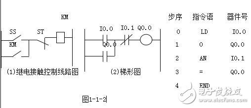
The instruction statement table is a language for programming PLC programs with instruction mnemonics. It is similar to computer assembly language, but it is easier to understand than assembly language. The program composed of several instructions is the instruction statement table. An instruction statement consists of three parts: the step sequence, the instruction word and the action device number.
The following example shows the two programming languages ​​for PLC implementation of three-phase squirrel cage motor start/stop control:
Brief list of SIMATIC basic instructions for the S7-200:
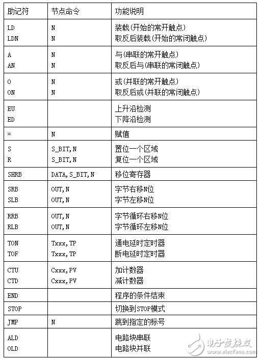
(Other instructions see attached table)
Standard contact instruction
The LD moving contact command indicates a moving contact command connected to the input bus, that is, the logical operation start of the moving contact.
The LDN break contact command indicates a break contact command that is connected to the input bus, that is, the start of the logical operation of the break contact.
A and dynamic contact command for series connection of single moving contacts.
AX and non-break contact command for series connection of single break contacts.
O or moving contact command for parallel connection of individual moving contacts.
ON or non-break contact command for parallel connection of individual break contacts.
The data type of the variable in the LD, LDN, A, AN, O, and ON contact commands is Boolean (BOOC) type. The LD and LDN commands are used to connect the contacts to the bus. The A, AN, O, and ON commands can be used repeatedly. However, when the parallel connection of two or more contacts in series is required, The OLD instruction described.
example:
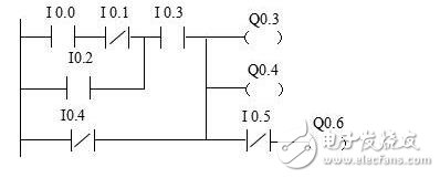
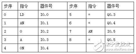
Parallel connection instruction OLD of series circuit block
A circuit in which two or more contacts are connected in series is called a series circuit block. When the series circuit blocks are connected in parallel, the branch starts with the LD and LDN instructions, and the branch ends with the OLD instruction. Both the OLD instruction and the ALD instruction described below are non-target component instructions, and the steps of the two non-target component instructions are one program step. OLD is sometimes referred to as a block instruction.
Series connection command ALD for parallel circuits
Two or more parallel circuits are called parallel circuit blocks. When the branch circuit parallel circuit blocks are connected in series with the previous circuit, the ALD command is used. The starting point of the branch is the LD and LDN instructions. After the parallel circuit is completed, the ALD instruction is used in series with the previous circuit. The ALD instruction is also referred to as a block instruction, and ALD is also a non-operation target component, which is a program step instruction.
Output instruction =
1. The output command is to directly connect the coil of the relay, timer, counter, etc. to the busbar on the right side of the ladder diagram. The right side of the coil does not allow contacts. In programming, the contacts are reused, and the type and quantity are not affected. limit.
Set and reset instructions S, R
S is a set instruction that keeps the action; R is a reset instruction that keeps the operation reset. The registers of N points starting from the specified position are all set or reset. N=1~255 If the timer bit or counter bit is specified to be reset, the current value of the timer or counter will be cleared.
Jump contact EU, ED
When the positive transition contact detects a positive transition (the input signal of the contact is from 0 to 1), or the negative transition contact detects a negative transition (the input signal of the contact is from 1 to 0), The point is turned on to a scan cycle. The signs of positive/negative transitions are EU and ED. They have no operands. The "P" and "N" in the middle of the contact symbol indicate positive and negative transitions, respectively.
Null operation instruction NOP
The NOP instruction is a step-by-step instruction with no action and no target component. The null operation instruction makes the step empty. The circuit can be changed by replacing the already written instruction with the NOP instruction. Add a NOP instruction to the program to reduce the step number change when changing or appending the program.
Program end command END
END is a step-by-step instruction with no target components. The PLC repeats input processing, program calculation, and output processing, and writes an END instruction at the end of the program to indicate that the program ends and directly performs output processing. During the program debugging process, the END instruction can be inserted in sections, and the inspection of each block motion can be expanded in order. The END instruction is used to divide the program into several segments. After confirming that the operation of the previous circuit block is correct, the END instruction is sequentially deleted. It should be noted that the watchdog clock is also refreshed when the END instruction is executed.
Five, programmable controller ladder programming rulesSeveral steps of programming
(1) Determine the actions and order required by the system.
When using a programmable controller, the most important part is determining the inputs and outputs required by the system. Input and output requirements:
The first step is to set the number of system inputs and outputs.
The second step is to determine the control sequence, the corresponding relationship of each device, and what kind of response.
(2) Numbers of input and output devices
Each input and output, including timers, counters, built-in registers, etc., has a unique number that cannot be mixed.
(3) Draw a ladder diagram.
Draw a ladder diagram according to the motion requirements of the control system.
Ladder design rule
(1) The contacts should be drawn on a horizontal line and drawn according to the left-to-right, top-down principle and the control path to the output coil.
(2) Branches that do not contain contacts should be placed in the vertical direction to facilitate identification of the combination of contacts and the control path to the output coil.
(3) When several series circuits are connected in parallel, the series circuit with more contacts should be placed at the top of the ladder diagram. When several parallel circuits are connected in series, the parallel circuit with the most contacts should be placed on the leftmost side of the ladder diagram. This arrangement has a simple and clear procedure and fewer statements.
(4) The contact cannot be drawn to the right of the coil.
Convert ladder diagrams into programs
Convert the relay ladder diagram into the code of the programmable controller. When the ladder diagram is completed, the next step is to compile its code into a program that the programmable controller can recognize.
This programming language consists of a sequence number (ie address), an instruction (control statement), and a device number (ie, data). The address is the location where the control statement and data are stored or placed. The instruction tells the programmable controller how to use the device to perform the corresponding action.
(5) Enter the program with the keyboard in the programming mode.
(6) Programming and design control procedures.
(7) Test the error of the control program and modify it.
(8) Preserving the complete control program.
Sixth, the function and working principle of the common relay control circuit combined with the corresponding PLCThe following is a diagrammatic explanation: the functions and working principles of the relay control circuit combined with the corresponding PLC are all part of the PLC basic knowledge.
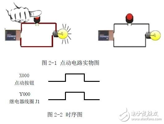
First, the jog circuit
Features:
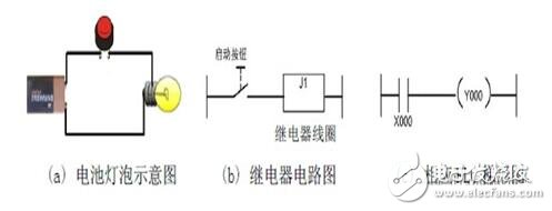
Working principle: As the name suggests, the point is moving, the loose is not moving, that is, pressing the button to open, release the button to stop.
Second, the automatic holding circuit with stop
Features
It is a basic form of maintaining the state of the circuit and is mainly used to maintain the state of the external signal.

working principle
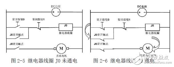
Turn on the power, press the normally open button 0, the relay coil J0 is energized, the J0 main contact is closed, and the motor is powered on. At the same time, the J0 auxiliary contact is self-locking and the motor continues to operate as shown in Figure 2-6. Stop and press the normally closed button 1. The relay coil J0 is de-energized, and the J0 auxiliary contact is disconnected. The motor is de-energized and stopped as shown in Figure 2-5.
Circuit application
Below we compare the relay coil before and after power-on and power-on:
Third, self-retaining interlock circuit
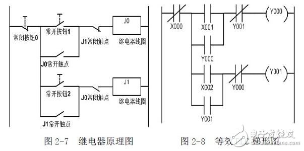
Features
One stop switch, two start switches, the signal that takes the first action first, the other signal is affected by the interlocking action, and does not act before the stop signal is not actuated.
working principle
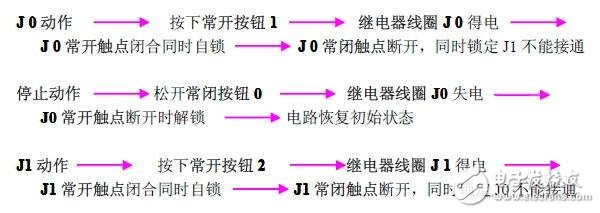
This circuit can be used for motor forward and reverse control.
Fourth, the first action priority circuit
Features
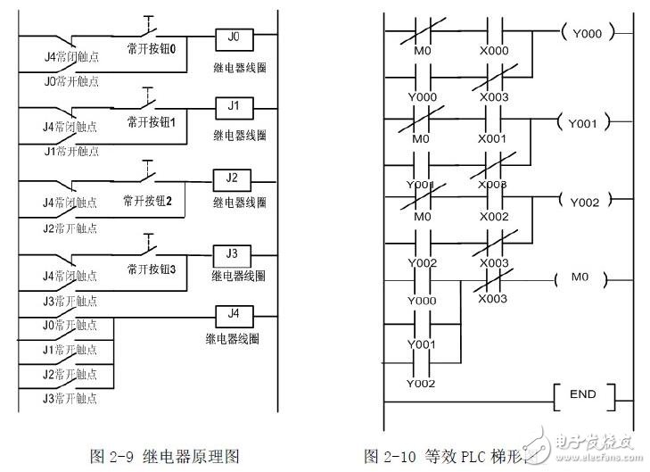
Among the lines of the plurality of input signals, the signal that is the first action takes precedence. When the first input signal is not removed, the other signals cannot be operated.
working principle
Normally open button 0 to 3 No matter which one is pressed, its corresponding relay coil is energized, the corresponding normally open contact is closed and self-locking, and the J4 relay also acts to disconnect the other 3 groups of power supply, as long as the first power is available. The relay is not powered and the other relays will not operate.
Circuit application
This circuit can be used as a responder as long as a reset switch is added to the power input.
Fifth, the post action priority circuit
Features
Among the lines of the plurality of input signals, the signal of the last action takes precedence. The state determined by the previous action is released by itself.
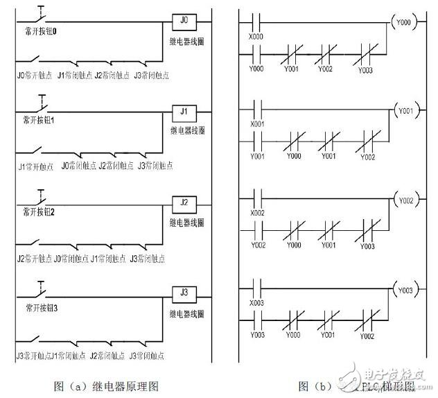
working principle
When the normally open button 0 to 3 is pressed in any state where the circuit is energized, the corresponding relay coil is energized, its corresponding normally closed contact is opened, and the self-locking (self-holding) state of the other coils is released.
Circuit application
This circuit can be added with a reset normally closed switch at the input end of the power supply for program selection, production period control circuit, and so on.
Sixth, time relay (also known as time delay relay)
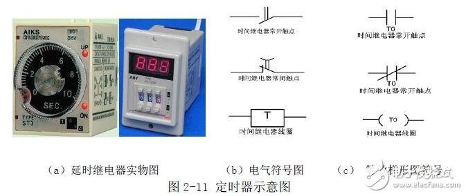
Features
When the input action signal is added (or removed), the output circuit must pass the specified precise time to generate a jump change (or contact action). The time relay is divided into on-delay and disconnect according to function. Delay, instantaneous delay, etc.

The following focuses on the application of time-delayed relays.
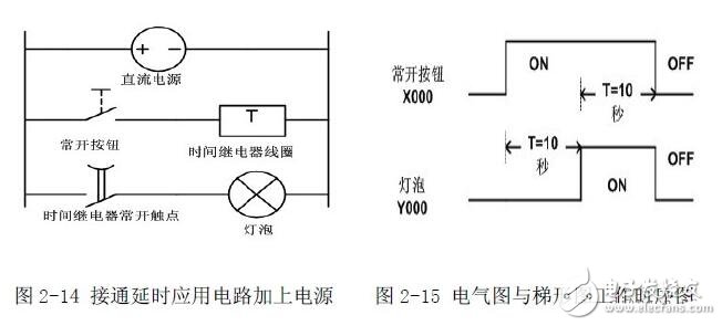
Figure 2-12 shows a simple delay-on application circuit. In order to facilitate the analysis principle, a light bulb is connected in series with the normally open contact of the time relay. Of course, you can also connect other loads in series, such as contactors, solid state relays, etc. Figure 2-13 shows the expression of PLC ladder diagram, schematic diagram and Figure 2 -12 is the same. In order to analyze the action flow, add power to the on-delay application circuit as shown in Figure 2-14, at which point the delay relay does not work.
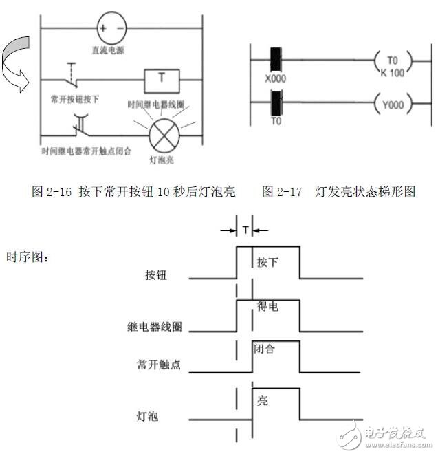
Assume that the preset time of the delay relay is 10 seconds. Press the normally open button, the time relay coil is energized and starts to count. After 10 seconds, the normally open contact is closed, and the bulb is energized. See Figure 2-16 until loose. When the normally open button is turned on, the time relay coil is de-energized, and the normally open contact returns to normal open. At this time, return to the state of Figure 2-14.
Seven, the counter
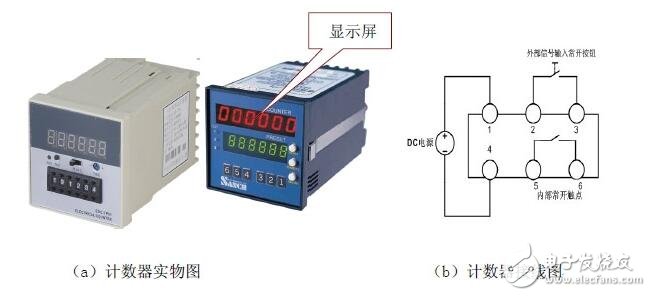
Features
The device is driven by the transmission mechanism to indicate the device to be measured (addition count) or inverse count (subtract count), and when the number reaches the preset value, the output is turned on or off.
The following describes the addition counting application.
Wiring instructions
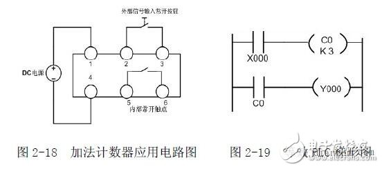
In Figure 2-18, pins 1 and 4 are power input terminals, pins 2 and 3 are signal input terminals, and pins 5 and 6 are internal normally open contact output terminals.
working principle
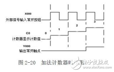
Press and release the normally open button once, and the counter display window is incremented by one. It is assumed that the preset value of the counter is 3. When the value of the normally open button is pressed and released three times, the internal normally open contact is closed.
Butt Connector,Lugs Insulated Female Connectors,Insulated Female Connectors,Non-Insulated Spade Terminals Wire Connector
Taixing Longyi Terminals Co.,Ltd. , https://www.lycopperlugs.com