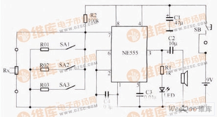
Moisture detection circuit
As shown in the multi-vibrator consisting of NE555 and R2, Rx and C4, the pulse signal output by the multivibrator sounds through the Speaker and emits a flash through the LED. If the resistance of Rx changes, the frequency of the multivibrator output pulse will also change, and this change can be judged by the comparison of the sounds.
The resistors RO1~R03 form the calibration resistance of the test circuit, and the three resistors are connected in parallel with the Rx circuit. As a resistance component of the oscillation circuit, the switches SAl~SA3 are used to control whether or not the circuit is connected.
When testing, first insert the probe into the tested product. After pressing the SB, you will hear the instrument emit a certain frequency and the LED will also emit a flash. Then pull out the probe and press a switch corresponding to the tested type in SAl~SA3, and then the instrument will hear the sound. Comparing the heights of the two sound frequencies before and after, if the pitch of the former sound is significantly higher than the pitch of the latter sound, the water content of the variety is higher.
Micro Speakers,Mininature Speaker,Mobile Phone Speaker,Multi Diaphragm Speaker
NINGBO SANCO ELECTRONICS CO., LTD. , https://www.sancobuzzer.com