Tuning and amplifying analog signals, it is a very versatile device that plugs into an appropriate feedback network and can be used as a supplier of precision AC and DC amplifiers, active filter filters, suppliers of oscillator oscillators, and voltages. The comparator comparator supplier. Its application areas have been extended to various fields such as automotive electronics, communications, and consumer, and will play an important role in future technologies.
Operational amplifier classificationOperational amplifiers can be divided into the following categories by parameters:
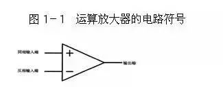
General-purpose operational amplifiers: The main features are low price, wide product range, and its performance indicators can be suitable for general use. Low-temperature drift type operational amplifier: In automatic control instruments such as precision instruments and weak signal detection, it is always desirable that the operational amplifier's offset voltage is small and does not change with temperature. High-impedance operational amplifier: The characteristic is that the differential mode input impedance is very high, and the input bias current is very small. Generally, rid>1GΩ~1TΩ, IB is several picoamperes to several tens of picoamperes. High Speed ​​Operational Amplifier: The main features are high slew rate and wide frequency response. Low-Power Operational Amplifiers: Since the biggest advantage of electronic circuit integration is that it can make complex circuits small and light, with the expansion of portable instrument applications, it is necessary to use low supply voltage, low power consumption op amps. High-Voltage, High-Power Operational Amplifiers: The output voltage of an op amp is primarily limited by the power supply. Programmable Control Operational Amplifier: The range is a problem when the instrument is used. In order to get a fixed voltage output, the op amp must be changed in magnification. Operational Operation of the Operational Amplifier The operational amplifier has two inputs and one output, as shown in Figure 1-1. The input labeled "+" is the "in-phase input" and cannot be called the positive terminal). The input with only the "one" sign is "inverting input" and can not be called the negative terminal. If the same signal is input from these two inputs, the voltage will be the same at the output but the opposite polarity. The output signal: the output signal of the output is in phase with the signal of the non-inverting input terminal, and is inverted with the signal of the inverting input terminal.
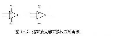
The power supply connected to the operational amplifier can be either a single power supply or a dual power supply, as shown in Figure 1-2. Op amps have some very interesting features that can be used flexibly to achieve many unique uses. In general, these features can be combined into two: 1. The op amp's magnification is infinite. 2. The input resistance of the operational amplifier is infinite and the output resistance is zero.
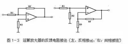
Now let's take a quick look at what conclusions can be drawn from the two features above. First, the op amp's amplification is infinite, so as long as the input voltage at its input is not zero, the output will have the same high output voltage as the positive or negative supply. It should be an infinitely high output voltage, but subject to Power supply voltage limit. To be precise, if the input voltage of the non-inverting input is higher than the input voltage of the inverting input, even if it is only a little high, the output of the op amp will output the same voltage as the positive supply voltage; The input voltage at the phase input is higher than the voltage input from the non-inverting input terminal. The output of the op amp outputs a voltage equal to the negative supply voltage (if the op amp uses a single supply, the output voltage is zero). Second, since the amplification factor is infinite, the op amp cannot be used directly as an amplifier. The output signal must be fed back to the inverting input (called negative feedback) to reduce its amplification. As shown in the left figure in Figure 1-3, the role of R1 is to return the output signal to the inverting input of the op amp. Since the inverting input is opposite to the output voltage, it will reduce the amplification factor of the circuit. Is a negative feedback circuit, and the resistor Rf is also called a negative feedback resistor.
Also, since the input to the op amp is infinite, there is no current input at the input of the op amp - it only accepts voltage. Similarly, if we imagine that there is an infinite resistance between the non-inverting input and the inverting input of the operational amplifier, then the voltage applied across the resistor cannot form a current, and there is no current. According to Ohm's law, the two ends of the resistor There will be no voltage, so we can think that the voltage at the two input terminals of the op amp is the same (the voltage in this case is a bit like shorting the two inputs with wires), so we call this phenomenon "Virtual short"). Common operational amplifier circuit
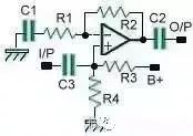
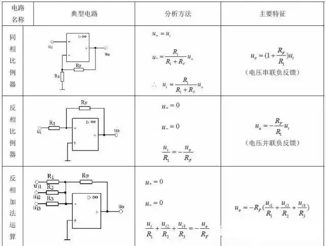
1. InverterAmp. Inverse phase amplification circuit:
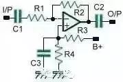
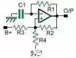
The magnification is Av=R2/R1 but the Gain-Bandwidth value of the specification needs to be considered. R3=R4 provides 1/2 power supply bias C3 for power supply decoupling filter C1, C2 input and output terminals are separated by DC, the output signal phase is opposite to the input end. 2. Non-inverterAmp.
Magnification is Av=R2/R1R3=R4 provides 1/2 power supply bias C1, C2, C3 is DC blocking. The output signal phase is the same as the input end. 3. Voltagefollower buffer amplifier circuit:
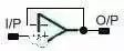
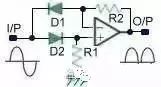
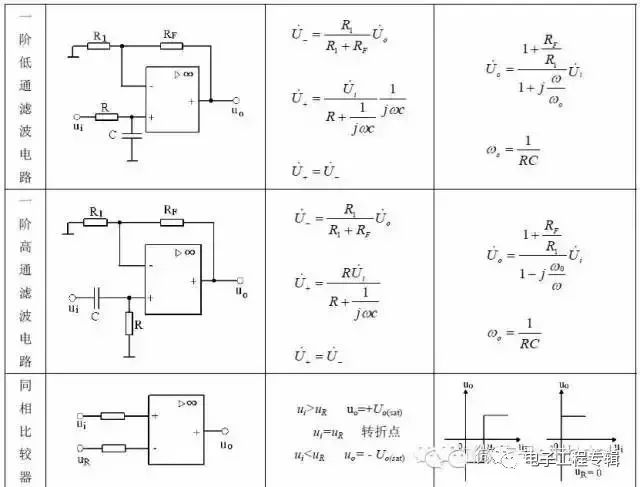
The potential of the O/P output is the same as the potential of the I/P input. Both single and dual power supplies can work. 4. Comparator comparator circuit:
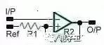
When the I/P voltage is higher than Ref, the O/P output is Logic low. When the I/P voltage is lower than Ref, the O/P output is Logic high potential R2=100*R1 to eliminate the Hysteresis state, that is, to strengthen O/ P output, Logic high and low potential difference to improve the sensitivity of the comparator. (R1 = 10K, R2 = 1M) single and dual power supply can work 5, Square-waveoscillator square wave oscillation circuit:
R2=R3=R4=100KR1=100K, C1=0.01uFFreq=1/(2Ï€*R1*C1) 6. Pulsegenerator pulse generator circuit:
R2=R3=R4=100K
R1=30K, C1=0.01uF, R5=150KO/P output OnCycle=1/(2Ï€*R5*C1)O/P output OffCycle=1/(2Ï€*R1*C1) 7. Activelow-passfilter active low Pass filter circuit:
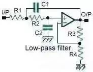
R1=R2=16KR3=R4=100KC1=C2=0.01uF Magnification Av=R4/(R3+R4)Freq=1KHz 8. Activeband-passfilter active bandpass filter circuit:
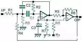
R7=R8=100K, C3=10uFR1=R2=390K, C1=C2=0.01uFR3=620, R4=620KFreq=1KHz, Q=25 9. High-passfilter high-pass filter circuit:
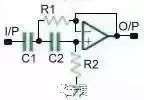
C1=2*C2=0.02uF, C2=0.01uFR1=R2=110K6dBLow-cutFreq=100Hz 10. Adj.Q-notchfilter bandwidth adjustable filter circuit:
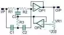
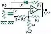
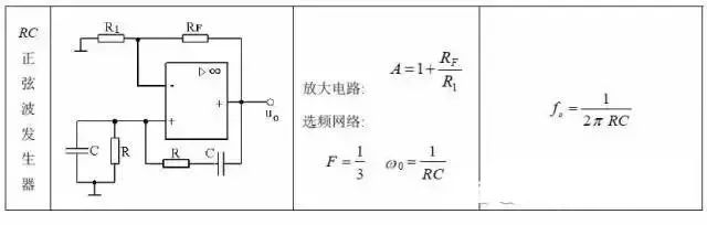
R1=R2=2*R3C1=C2=C3/2Freq=1/(2Ï€*R1*C1) VR1 adjusts the negative feedback amount, and the larger the Q value, the lower the Q value. (This indicates that the frequency band is widened, but the attenuation value is relatively reduced.) R1, R2, R3, C1, C2, and C3 are Twin-Tfilter structures. 11, Wien-bridgeSine-waveOscillator bridge sine wave oscillation circuit:
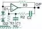
R1=R2, C1=C2R3 and D1, D2Zener generates fixed-point pressure negative feedback Freq=1/(2Ï€*R1*C1) D1 and D2 can use Lamp effect better (generating impedance negative coefficient of variation) 12. Peakdetector peak detection Circuit: (examples are positive peak detection)

This circuit only provides a reference for thinking (the right circuit has amplifying function) Eo=Ei*(R4+R3)/R3S1 is a continuous sampling switch, and the peak value is constantly changing. 13, Positive-peakdetector positive peak detector circuit:
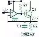
R1=1K, R2=1M, C1=10uF Only when the I/P potential is higher than the OP-terminal potential, Q1 can be turned on, and the O/P potential continues to rise. The positive peak must be lower than the positive value of the power supply. Is the highest value. 14, Negative-peakdetector negative peak detector circuit:
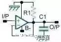
R1=1M, C1=10uF Only when the I/P potential is lower than the OP-terminal potential, the O/P potential continues to decrease. The negative peak must be higher than the negative value of the power supply, and the obtained data is the highest value. 15, RMS (Absolutevalue) detector absolute value detector circuit:
Regardless of the polarity of the I/P terminal, it can be output by the O/P terminal. If the back end is connected to the positive peak detector circuit, the RMS value can be obtained.
Classical op amp circuit analysis from the virtual break, virtual short analysis of the basic op amp circuit The operational amplifier consists of a variety of circuits, dazzling, is the focus of learning in analog circuits. When you analyze the working principle of it, if you don't grasp the core, it is often big. To this end, I specially searched the application of the world's operational amplifier circuit, and came to a "King Ding Jie Niu". I hope that you will gain some after reading. Throughout the books and courses of all analog electronic technology, when introducing the operational amplifier circuit, it is only to first characterize the circuit, such as this is a non-directional amplifier, and then derive its output and input relationship, and then draw Vo=(1+Rf)Vi, that is an inverting amplifier, and then we get Vo=-Rf*Vi... Finally students often come up with the impression that remembering the formula is fine! If we change the circuit a little, they can't find the North! Today, I teach you two invincible moves. These two tricks are written in the textbooks of all op amp circuits. They are "virtual short" and "virtual break", but if you use it to get rid of it, you have to compare it. Deep foundation. The concept of virtual short and virtual break Because the op amp's voltage amplification is large, the general-purpose operational amplifier's open-loop voltage amplification is above 80dB. The output voltage of the op amp is limited, generally 10V ~ 14V. Therefore, the differential mode input voltage of the op amp is less than 1 mV, and the two inputs are approximately equipotential, which is equivalent to "short circuit". The larger the open-loop voltage amplification factor, the closer the potentials at the two inputs are equal. “Virtual short†means that when the operational amplifier is in a linear state, the two inputs can be regarded as equipotential. This characteristic is called false short circuit, which is called virtual short. Obviously you can't really short the two inputs. Since the differential mode input resistance of the op amp is large, the input resistance of a general-purpose operational amplifier is above 1 MΩ. Therefore, the current flowing into the input of the op amp is often less than 1uA, which is much smaller than the current of the circuit outside the input. Therefore, the two inputs of the op amp can usually be regarded as open circuits, and the larger the input resistance, the closer the two input terminals are to the open circuit. “Dummy†means that when the analysis op amp is in a linear state, the two inputs can be regarded as equivalent open circuits. This feature is called a false open circuit, which is called virtual break. Obviously you can't really break the two inputs. When analyzing the working principle of the op amp circuit, first of all, please forget what the same direction amplification, reverse amplification, what adder, subtractor, what differential input... temporarily forget the formula of the input and output relationship... these Dongdong only It will interfere with you and make you more confused. Please also ignore the input circuit parameters such as bias current, common mode rejection ratio and offset voltage. This is something designers should consider. What we understand is the ideal amplifier (in fact, in the maintenance process and most of the design process, the actual amplifier will not be a problem if it is an ideal amplifier). Ok, let's grab two "axes" ------ "virtual short" and "virtual break", and start "King Ding Jie Niu". 1) Inverting amplifier: 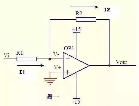
Figure 1 The op-amp grounding of the op amp is grounded = 0V, the inverting terminal and the inverting terminal are short and short, so it is also 0V. The input resistance of the inverting input terminal is very high, and there is almost no current injection and outflow, so R1 and R2 are equivalent. Thus, the current flowing through each of the components in a series circuit is the same, that is, the current flowing through R1 and the current flowing through R2 are the same.
Current flowing through R1: I1=(Vi-V-)/R1.........a current flowing through R2: I2=(V--Vout)/R2...bV-=V+=0.................. cI1=I2........................d Solve the above junior high school algebra equation to get Vout=(-R2/R1)*Vi This is the input and output relationship of the legendary inverting amplifier. 2) Co-directional amplifier
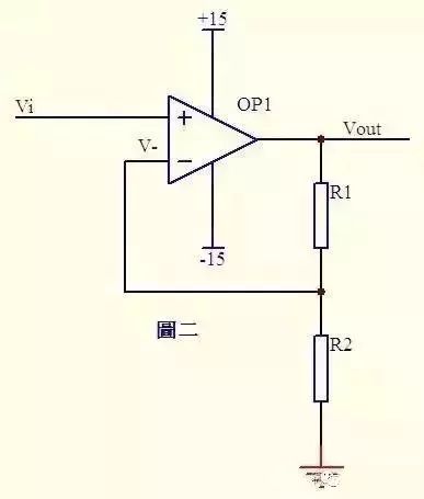
In Fig. 2, Vi and V-virtual are short, then Vi=V-...a is a virtual disconnection, there is no current input and output at the inverting input, the current through R1 and R2 is equal, and the current is I, which is obtained by Ohm's law: I=Vout/(R1+R2)...bVi is equal to the partial pressure on R2, ie: Vi=I*R2...c is abc-type Vout=Vi*(R1+R2)/R2 This is the legendary same The formula to the amplifier. 3) Adder 1:
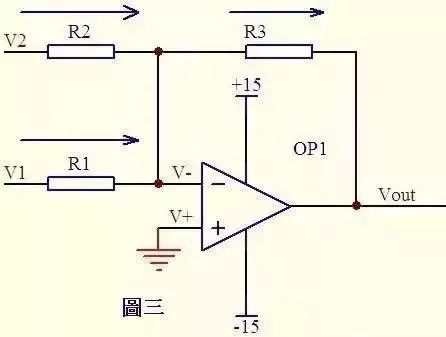
In Figure 3, it is known from the virtual short: V-=V+=0...a is known from the virtual break and Kirchhoff's law. The sum of the currents through R2 and R1 is equal to the current through R3, so (V1–V-) /R1+(V2–V-)/R2=(V-–Vout)/R3...b substitutes for a, and b becomes V1/R1+V2/R2=Vout/R3. If R1=R2=R3, then The above formula becomes -Vout=V1+V2, which is the legendary adder. 4) Adder 2:
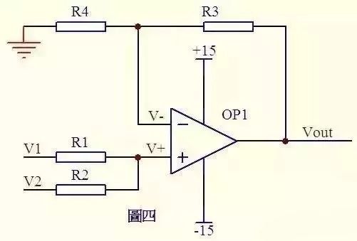
Please see Figure 4. Because there is no current flowing through the same direction of the op amp, the current flowing through R1 and R2 is equal, and the current flowing through R4 and R3 is also equal. Therefore (V1–V+)/R1=(V+-V2)/R2...a(Vout–V-)/R3=V-/R4...b is known by the virtual short: V+=V-...c if R1= R2, R3 = R4, then the above formula can be derived V + = (V1 + V2) / 2V - = Vout / 2, so Vout = V1 + V2 is also an adder, huh! 5) Subtractor
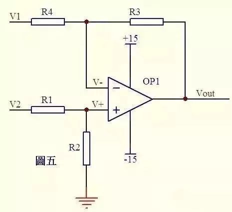
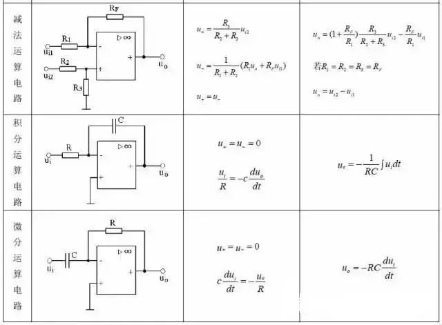
Figure 5 is known from the virtual break. The current through R1 is equal to the current through R2. Similarly, the current through R4 is equal to the current in R3, so there is (V2–V+)/R1=V+/R2...a(V1–V-) /R4=(V--Vout)/R3...b If R1=R2, then V+=V2/2...c If R3=R4, then V-=(Vout+V1)/2...d is short Know V+=V-...e so Vout=V2-V1 This is the legendary subtractor. 6) Integral circuit:
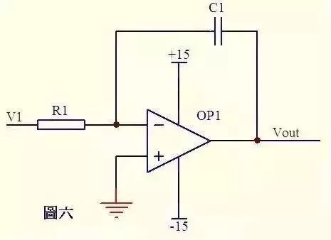
In the circuit of Figure 6, it is known from the virtual short that the voltage at the inverting input is equal to the same end.
It is known from the virtual break that the current through R1 is equal to the current through C1. The current through R1 is i=V1/R1 through the current of C1 i=C*dUc/dt=-C*dVout/dt, so Vout=((-1/(R1*C1))∫V1dt output voltage and input voltage versus time The integral is proportional, this is the legendary integration circuit. If V1 is a constant voltage U, then the above equation is transformed into Vout=-U*t/(R1*C1)t is time, then the Vout output voltage is one from 0. Straight line to the negative supply voltage as a function of time. 7) Differential circuit:
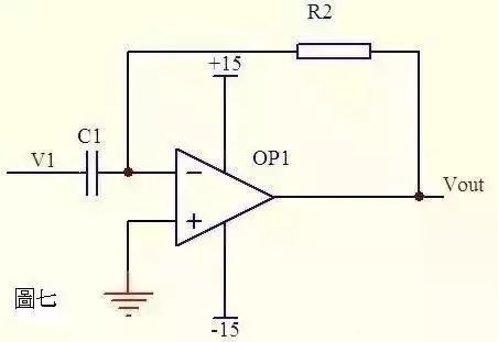
In Figure 7, it is known from the virtual break that the current through capacitor C1 and resistor R2 is equal. From the virtual short, the voltages at the same end and the opposite end of the op amp are equal. Then: Vout=-i*R2=-(R2*C1)dV1/dt This is a differential circuit. If V1 is a sudden addition of DC voltage, the output Vout corresponds to a pulse in the opposite direction to V1. 8) Differential amplifier circuit
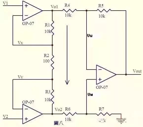
It is known from the virtual short-term Vx=V1...aVy=V2...b that there is no current flowing through the input of the op amp, then R1, R2, and R3 can be regarded as series, and the current through each resistor is the same. Current I=(Vx-Vy)/R2...c then: Vo1-Vo2=I*(R1+R2+R3)=(Vx-Vy)(R1+R2+R3)/R2...d The current flowing through R6 is equal to the current flowing through R7. If R6=R7, then Vw=Vo2/2...e. Similarly, if R4=R5, then Vout–Vu=Vu–Vo1, so Vu=(Vout+Vo1) /2...f is known by the virtual short, Vu=Vw...g is obtained by efgVout=Vo2–Vo1...h from dhVout=(Vy–Vx)(R1+R2+R3)/R2 R1+R2+R3)/R2 is a fixed value that determines the magnification of the difference (Vy–Vx). This circuit is the legendary differential amplifier circuit. 9) Current detection:
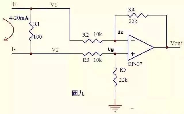
Analyze a circuit that everyone has touched more. Many controllers accept 0~20mA or 4~20mA current from various instruments. The circuit converts this current into voltage and then sends it to the ADC to convert it into a digital signal. Figure 9 is such a typical circuit. As shown in Figure 4~20mA current flows through the sampled 100Ω resistor R1, a voltage difference of 0.4~2V is generated on R1. It is known from the virtual disconnection that there is no current flowing through the input of the op amp, and the current flowing through R3 and R5 is equal, and the current flowing through R2 and R4 is equal. Therefore:
(V2-Vy)/R3=Vy/R5...a(V1-Vx)/R2=(Vx-Vout)/R4...b is known by the virtual short: Vx=Vy...c current varies from 0 to 20 mA, Then V1=V2+(0.4~2)...d is obtained by substituting cd into b (V2+(0.4~2)-Vy)/R2=(Vy-Vout)/R4...e if R3=R2, R4=R5 , from ea Vout = - (0.4 ~ 2) R4 / R2 ... f Figure 9 R4 / R2 = 22k/10k = 2.2, then f-type Vout = - (0.88 ~ 4.4) V, that is to say, will The 4~20mA current is converted to a voltage of -0.88~-4.4V, which can be sent to the ADC for processing. Note: If the current of Figure 9 is reversed, Vout=+(0.88~4.4)V, 10) voltage and current conversion detection:
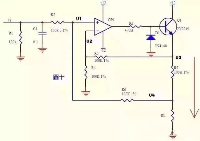
The current can be converted to a voltage and the voltage can be converted into a current. Figure 10 is such a circuit. The negative feedback in the above figure does not pass the direct feedback of the resistor, but the emitter junction of the transistor Q1 is connected in series. You should not think that it is a comparator. As long as it is an amplifying circuit, the law of virtual short and short break is still consistent! It is known from the virtual break that there is no current flowing through the input of the op amp, then (Vi–V1)/R2=(V1–V4)/R6...a is the same (V3–V2)/R5=V2/R4...b Virtual short-term knowledge V1=V2...c If R2=R6, R4=R5, then abc formula V3-V4=Vi The above equation shows that the voltage across R7 is equal to the input voltage Vi, then the current through R7 is I=Vi/ R7, if the load RL<<100KΩ, the current through R1 and through R7 is substantially the same. 11) Sensor detection:
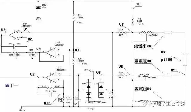
Come to a complicated one, huh! Figure 11 is a three-wire PT100 preamplifier circuit. The PT100 sensor leads out three wires with the same material diameter, wire diameter and length. The connection is shown in the figure. A voltage of 2V is applied to the bridge circuit consisting of R14, R20, R15, Z1, PT100 and its line resistance. Z1, Z2, Z3, D11, D12, D83 and each capacitor play the role of filtering and protection in the circuit. It can be ignored during static analysis. Z1, Z2, Z3 can be regarded as short circuit, D11, D12, D83 and each capacitor can be seen. For the road. Known by resistor divider, V3=2*R20/(R14+20)=200/1100=2/11...a is known by the virtual short, U8B pin 6 and pin 7 and pin 5 voltage are equal V4=V3... ...b is known by the virtual break, no current flows through the second leg of U8A, and the current flowing through R18 and R19 is equal. (V2-V4)/R19=(V5-V2)/R18...c is known by virtual disconnection, there is no current flowing through the third leg of U8A, V1=V7...d in the bridge circuit R15 and Z1, PT100 and line resistance In series, the voltage divided by PT100 and the line resistance is added to the third leg of U8A through resistor R17. V7=2*(Rx+2R0)/(R15+Rx+2R0).....e is known by the virtual short, U8A The voltages of pin 3 and pin 2 are equal, V1=V2...f is obtained by abcdef, (V5-V7)/100=(V7-V3)/2.2 is reduced to V5=(102.2*V7-100V3)/2.2 is V5 =204.4(Rx+2R0)/(1000+Rx+2R0)–200/11...g The above output voltage V5 is a function of Rx. Let us look at the effect of line resistance. The voltage drop generated at the bottom line resistance of Pt100 passes through the middle line resistance, Z2, R22, and is added to the 10th pin of U8C. It is known from the virtual break, V5=V8=V9=2*R0/(R15+Rx+2R0) ...a(V6-V10)/R25=V10/R26...b is known from the virtual short, V10=V5...c is obtained by the formula abcV6=(102.2/2.2)V5=204.4R0/[2.2(1000+Rx +2R0)]...h The equations consisting of the formula gh know that if the values ​​of V5 and V6 are measured, Rx and R0 can be calculated. Knowing Rx, the pt100 index table knows the temperature. Operational amplifier typical application circuit and analysis overview

LANA Vape Device/Battery is so convenient, portable, and small volume, you can buy a corresponding lana pod with an atomizer to make a combination, this is just an electronic cigarette battery with a mod, and it does not fully work.
We are China leading manufacturer and supplier of Disposable Vapes puff bars, lana vape device/battery adapter,lana vape device batteries and charger,
lana vape device/battery electric, and e-cigarette kit, and we specialize in disposable vapes, e-cigarette vape pens, e-cigarette kits, etc.
lana vape device/battery adapter,lana vape device batteries and charger,lana vape device/battery electric,lana vape device batteries e-cig,lana vape device/battery jump starter
Ningbo Autrends International Trade Co.,Ltd. , https://www.supermosvape.com