Backlights are used in small and light-weight electronic devices such as flat-panel liquid crystal displays (LCDs) that require backlighting, ranging from hand-held devices such as palm-sized to large-screen TVs. The goals of backlight design include low power consumption, ultra-thin, high brightness, uniform brightness, large area, and different wide and narrow viewing angle controls. In order to achieve these challenging design goals, and to control costs and achieve fast, must use computer-aided optical design tools for design. This article introduces the characteristics of LightTools optical design and analysis software of ORA Corporation of the United States, which can be used to develop the most advanced backlight design applications today.
Optical design and analysis tools for backlighting
The backlighting system needs to convert the light from one or more light sources to produce a required light distribution in an area or a fixed angle. The lighting design software must be able to geometrically model, set optical characteristic parameters for different types of light sources and conversion units, and must be able to use optical tracing methods to evaluate the path of light through the model and calculate the final light distribution. The light distribution uses Monte Carlo simulation to calculate illuminance, brightness, or luminous intensity for a specific area and / or angle. The light is emitted from the light source at random positions and angles, traced through the optical system, and received on the receiving surface. The illuminance can be calculated from the surface receiver, and the intensity can be obtained from the far field receiver. By defining a brightness meter on the surface of the receiver, the distribution of brightness with space and angle can be calculated. In some cases, it may be important to analyze the chromaticity of the display. Specify the spectral energy distribution of a light source (such as a light-emitting diode), output CIE coordinate values ​​and correlated color temperature (CCT), quantify the chromaticity of the display, and generate RGB real light rendering graphics on the display. These analyses can be done in LightTools software.
The characteristics of the backlit display have special requirements for the lighting analysis software. As will be explained, the light emitted by the backlight depends on the distribution density of the printed dots, or the distribution pattern of the microstructures. For the modeling of a specific microstructure array, if the CAD model is used directly, it may result in a very large model size. LightTools software provides the function of three-dimensional texture array definition, which can perform accurate ray tracing and rendering. Since the geometric model directly constructed is not used, the model has a smaller size and faster ray tracing. Another aspect of backlight analysis includes the splitting and scattering of light on the surface of the light guide plate. Since the Monte Carlo method is used to simulate the lighting effect, it may be necessary to use a lot of ray tracing to obtain a sufficiently accurate design. The most effective way is to trace the highest energy light. By using the spectral probability to trace the path of the highest energy ray, and using the target area or scattering angle of the scattering surface to direct the scattered light to an "important" direction (such as towards the observer of the display).
What is backlight?
A typical backlight consists of a light source, such as a cold cathode fluorescent lamp (CCFL) or light emitting diode (LED), and a rectangular light guide plate. Other available components include a diffuser plate to improve the uniformity of the display, and a brightness enhancement film (BEF) to increase the brightness of the display. The light source is usually located on one side edge of the light guide plate to reduce the thickness of the display. Side-light illumination usually uses total reflection (TIR) ​​to conduct light in the display.
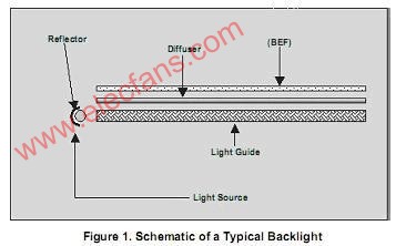
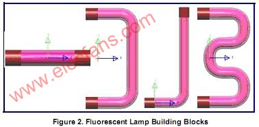
Figure 1 shows a typical backlight design schematic.
Backlight designers have multiple methods for modeling light sources in LightTools software. Different shapes of fluorescent light sources (such as straight, L-shaped, U-shaped or W-shaped, as shown in Figure 2) can be quickly defined using the fluorescent lamp creation tool. The reflector of the lamp can be defined by various geometric prototypes in the LightTools software, such as cylinders, elliptical grooves, and extruded polygons. The reflectors defined in the CAD system can also be imported into LightTools software through standard data exchange formats (IGES, STEP, SAT and CATIA). If using LEDs, designers can choose the desired LED model from the product models of Agilent, Lumileds, Nichia, Osram and other companies pre-stored in LightTools software. Once the light enters one side of the light guide plate, the problem becomes to extract light from the light guide plate perpendicular to the direction of propagation.
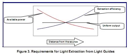
As shown in Fig. 3, the brightest in the light guide plate is the side close to the light source. As the distance increases, the brightness in the light guide plate becomes darker. In order to obtain a uniform light output, the light extraction efficiency must increase as the distance increases. One of the main tasks of backlight design is to design light guide plates that change the light extraction efficiency as needed. There are two extraction techniques that can be used. The dot printing light extraction technology is to print a dot matrix structure on the bottom of the light guide plate to scatter the light upwards and emit it from the surface of the light guide plate. The second technology, compression molding light extraction technology, relies on total reflection (TIR) ​​of the bottom surface microstructure to cause light to exit from the surface of the light guide plate.
LightTools software provides backlight design tools to realize the design of light guide plates. This tool (Figure 4) assists the user in creating various components of the backlight. Other options include adding light source / reflector components to the model, BEF modeling, and building a receiver to analyze brightness. The interface of the backlight tool is a plurality of tabs, which are used to set and modify various different types of light extraction mechanisms.
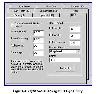
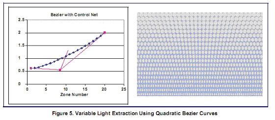
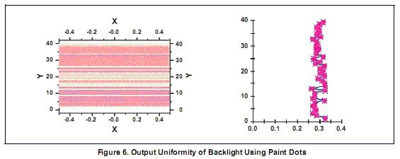
For the backlight using the dot printing light extraction method, the backlight tool can set the linear change of the size and aspect ratio of the printed dots, and the linear change of the dot pitch along the length of the light guide plate. This linearly changing structure is often a good starting point for displaying uniformity, but it is not enough to meet the final uniformity requirements. Further control of uniformity can use nonlinearly varying light extraction parameters. A method that uses the fewest parameters and is very flexible to control is to define the parametric variables of the quadratic Bezier curve. LightTools software's 2D area tools can be used to set up nonlinear structures. Figure 5 shows an example of using printing extraction, in which three parameters (printed dot width, height and vertical spacing) are varied to obtain different extraction behaviors. The output uniformity is shown in Figure 6. The figure on the right shows that the average output brightness is a constant.
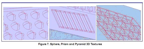
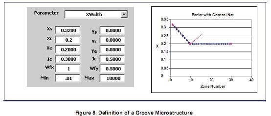
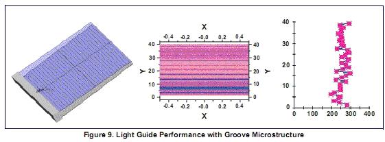
 The second extraction method, compression molding extraction technology, uses the three-dimensional texture function of LightTools software, which makes the ray tracing of repeated structures very effective and the storage information is very compact. The ray trace of the model created by the non-3D texture function is more than 30 times slower than the model created by the 3D texture, and the file is more than 100 times larger. Three basic shapes are available for three-dimensional textures: spherical, prismatic, and pyramidal (Figure 7). Backlight tools can define linearly variable microstructures. But 3D texture tools can use quadratic Bezier curves to change the texture parameters non-linearly. The example shown in Figure 8 is a groove-shaped microstructure (using prismatic 3D texture modeling) as the extraction mechanism. The resulting light guide plate and its simulation results are shown in Figure 9.
Backlight optical calculation
The two most important optical quantities of a backlit display are the display brightness and illuminance uniformity on the surface of the light guide plate. It is also important to calculate the luminous intensity and various color metrics (CIE coordinates and correlated color temperature CCT). LightTools software has built-in these calculation functions and many other functions to help understand the data generated by Monte Carlo simulation.
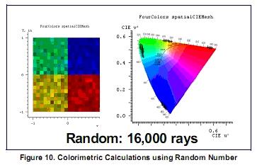
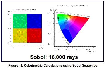
Monte Carlo simulation is the basis of LightTools software to calculate illuminance. The random number generator is used to select the starting position, direction and wavelength of the light, and is used to sample the light distribution on the receiving surface. The choice of "random" numbers will greatly affect the convergence of the simulation. Using a low-difference (Sobol) number sequence (it is not completely random), the error can be reduced to 1 / N, where N is the number of rays at the receiving end. You can see the comparison result of calculating the chromaticity using the random number sequence (Figure 10) and the Sobol number sequence (Figure 11). In this example, the simulation result using 128,000 random rays is equivalent to the accuracy of Sobol's 16,000 rays. The important thing is to compare the simulation convergence speed of different software. What we care about is the speed to achieve a certain simulation accuracy, not the speed to trace a certain amount of light. In LightTools software, the receiver is used to collect light data to calculate illuminance.
The light data for analysis and display is collected from the data grid. Users can interactively control the size or number of data grids. For a given number of rays on the receiver, the smaller the number of grids, the lower the spatial and angular resolution, but the higher the relative accuracy (low error rate). Conversely, the greater the number of grids, the higher the spatial and angular resolution, but the lower the accuracy (high error rate). The estimated error rate is displayed on each grid to help users decide whether enough light is used for tracking simulation to meet the resolution and accuracy required by the design (Cassarly, WJ, Fest, EC, and Jenkins, DG , 2002). If more light is needed, the user can continue the simulation interactively until the goal is reached.
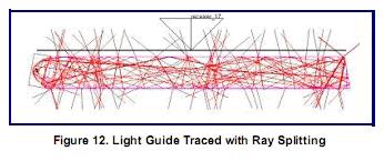
An important aspect of backlight analysis is the light splitting and scattering on the surface of the light guide plate. The function of the light guide plate is that the light can be absorbed or emitted after being reflected multiple times on the inner surface. If the light is split into transmission and reflection at each contact surface, it will cause a very large amount of split light, most of which do not carry much energy, which slows down the analysis speed. An example of this is shown in Figure 12, which shows a starting ray, many paths due to splitting.
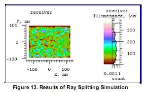
The following simulation uses 2000 incident rays. Due to the splitting, the receiver collected 277,948 rays (Figure 13). Since most of the light reaching the receiver does not have much energy, the resulting error is 42%. On the contrary, if the Fresnel loss coefficient and surface scattering characteristics are used to determine the possibility of light transmission and reflection to evaluate the possibility of the optical path, most of the time the ray trace will be used to track the energy in the system Speed ​​up analysis. A simulation result of 200,000 incident rays is shown in Figure 14. In this case, 118,969 rays reach the receiver, and the calculation error is 6%. Using probabilistic ray tracing reduced the calculation error by a factor of 7 while reducing the calculation time by 42%.
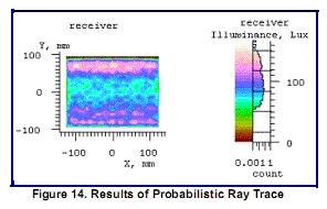
On the contrary, if the Fresnel loss coefficient and surface scattering characteristics are used to determine the possibility of light transmission and reflection to evaluate the possibility of the optical path, most of the time of ray tracing will be used to track the energy in the system, thus Speed ​​up analysis. A simulation result of 200,000 incident rays is shown in Figure 14. In this case, 118,969 rays reach the receiver, and the calculation error is 6%. Using probabilistic ray tracing reduced the calculation error by a factor of 7 while reducing the calculation time by 42%.
Finally, in order to improve the uniformity of the display, a diffusion plate is sometimes used on the top surface of the light guide plate. Because the diffuser diffuses light to a wider angle, less light is scattered into the aperture of the brightness meter, and according to the conventional display brightness test method, a very large amount of light is required for brightness calculation. LightTools software maps the target area or angle to the scattering surface, allowing the user to specify which scattering should be considered. This is an important form of sampling and another method to improve the convergence of Monte Carlo simulations. Figure 15 shows a brightness meter and backlight with diffuser plate, without specifying the target angle. Tracing 2000 rays, the brightness meter received 40 rays, and the spatial brightness raster is shown in the figure.
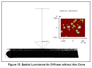
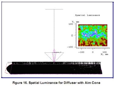
Figure 16 shows the same example, but sampling by important values, the target angle is specified on the diffuser. The target angle matches the acceptance angle of the luminometer aperture. When the light reaches the diffuser, the LightTools software will generate scattered light (the luminous flux estimated into the target area based on the angular distribution of the diffusion model) into the target angle, so that all the scattered light collected by the brightness meter will improve the convergence of the simulation. In this case, 2000 incident rays and 1416 rays (71%) were received by the brightness meter.
Other considerations
Backlights are widely used in liquid crystal displays (LCDs), which are a type of polarization component. Modeling polarization components, such as linear polarization, quarter-wavelength plates, and polarized light tracking evaluation are critical factors for successful analysis. LightTools software provides simple linear polarization and retardation models, as well as Jones-Mueller matrix specifications for polarization components. Users can use the polarized ray tracing function to track the polarization state of light according to the Stocks vector when needed.
Often there are various optical coatings with different transparency, reflection coefficient and polarization characteristics on the components. The coating is defined in LightTools software based on its performance, which is often the only information the user knows. The average or individual S or P values ​​of reflection and transmission can be specified by any of the following two parameters: angle of occurrence, wavelength, X position, or Y position. The system provides tools to convert the coating stack into the LightTools software coating format.
Although most backlights use dot printing or compression molding light extraction techniques, other methods are also possible. One is to use particle scattering in the light guide plate. If the particle size and density are properly controlled, Mie scattering from particles can effectively extract light from the light guide plate (Tagaya, et al., 2001: 6274). LightTools software can simulate the scattering of spherical particles in batches according to Mie theory, or according to the angle distribution defined by the user.
Exporting a complete optical design to a CAD system is often a necessary step for manufacturing a light guide plate. LightTools software supports standard format conversions such as STEP, SAT, or IGES to complete. Since the data conversion standard only supports external geometric data, in the case of compression molding design extraction, the shape defined by the three-dimensional texture needs to be converted into external geometric data output. LightTools software supports standard formats and can optionally convert 3D textures to external geometric data, so that the entire backlight design is included in the conversion file.
summary
The backlight design technology has been constantly progressing and developing to provide better performance and lower cost to meet market demands. This innovation requires lighting design software to continuously add new features, especially support for shortening the backlight design cycle. The main functions of LightTools software such as model creation and file size, ray tracing and simulation time, and the function of calculating a large number of optical parameters related to backlight design have all been recognized and verified by the industry.
Version 5.0 of the LightTools software released in 2004 includes noise-redundant illumination optimization, which is very practical in backlight design. This function can automatically define the light extraction template to achieve maximum efficiency and uniformity. In addition, the backlight template optimization tool of LightTools software provides an effective method for optimizing the output distribution of backlight and light guide.
BLPS laser safety protective device is designed for personal safety used on hydraulic bender.
The dynamic test technology it used has passed the Type 4 functional safety assessment by TUV, and get the national invention patent. The product reaches the advanced technological level of similar products.
BLPS laser safety device provides protection zone near the die tip of the bender to protect fingers and arms of the operator in close to the upper mold die tip. It is the most effective solution so far to preserves the safety and productivity of the bender.
Press Brake Protection,Laser Guarding Device,Press Brake Guarding Systems,Press Brake Guarding
Jining KeLi Photoelectronic Industrial Co.,Ltd , https://www.sdkelien.com