A photoelectric encoder is a sensor that converts the amount of mechanical geometric displacement on an output shaft into a pulse or digital quantity by photoelectric conversion. This is the most widely used sensor, and the photoelectric encoder is composed of a grating disk and a photoelectric detecting device. The grating disk is opened in a plurality of rectangular holes equally on a circular plate of a certain diameter. Since the photoelectric code disk is coaxial with the motor, when the motor rotates, the grating disk rotates at the same speed as the motor, and a detection device composed of electronic components such as light-emitting diodes detects and outputs a plurality of pulse signals.
The current motor speed can be reflected by calculating the number of photoelectric encoder output pulses per second. In addition, to determine the direction of rotation, the code wheel can also provide a phase difference of 90. According to the detection principle, the encoder can be divided into optical, magnetic, inductive and capacitive. According to its scale method and signal output form, it can be divided into three types: incremental, absolute and hybrid.
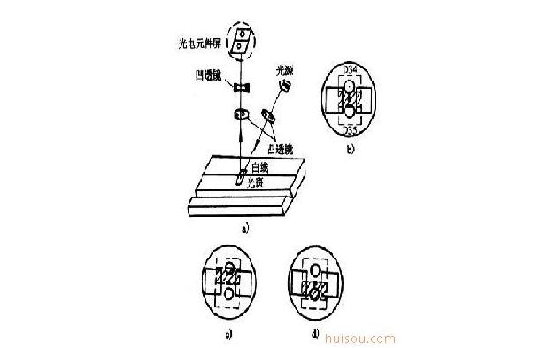
Photoelectric sensor circuit diagram

a) Photoelectric circuit diagram
b) Photoelectric sensor circuit diagram line centered
c) Photoelectric sensor circuit diagram line to the left
d) Photoelectric sensor circuit diagram line is right
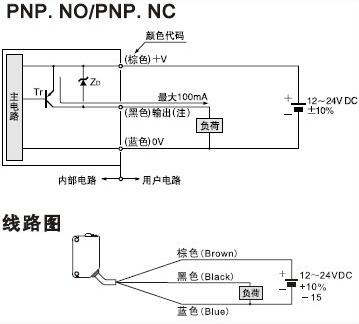
Photoelectric sensor wiring diagram

Fork Type Terminals,Insulated Bullet Sockets Terminals,Insulated Bullet Terminals,Type Fork Insulate Terminal
Taixing Longyi Terminals Co.,Ltd. , https://www.longyicopperlugs.com