Electronic circuits typically operate at a positive regulated output voltage, which is typically provided by a buck regulator. If a negative output voltage is also required, the same buck controller can be configured in a buck-boost topology. Negative Output Voltage Buck-Boost is sometimes referred to as a negative inversion with an operating duty cycle of 50%, which provides an output voltage equivalent to the input voltage but opposite in polarity. It can adjust the duty cycle with fluctuations in the input voltage and maintain regulation with a “buck†or “boost output voltageâ€.
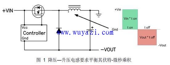
Figure 1 shows a thin buck-boost circuit with the switching voltage present on the inductor. In this way, the similarity between the circuit and the standard buck converter will suddenly become clear. In fact, it is exactly the same as the buck converter except that the output voltage is the opposite of the ground. This layout can also be used for synchronous buck converters. This is similar to the buck or synchronous buck converter side because it operates differently than a buck converter. 
The voltage appearing on the inductor when the FET is switched is different from the voltage of the buck converter. As in buck converters, it is necessary to balance the volt-microsecond (V-μs) product to prevent inductor saturation. When the FET is on (as in the ton interval shown in Figure 1), all input voltage is applied to the inductor. This inductor, the positive voltage on the side of the point, causes the current to ramp up, which leads to the product's turn-on time V-μs product. During the FET turn-off (toff), the voltage polarity of the inductor must be reversed to maintain the current so that the pull side is negative. The inductor current ramps down and flows through the load and output capacitors and back through the diode. The V-μs product when the inductor is turned off must be equal to the V-μs product at turn-on. Since Vin and Vout are unchanged, it is easy to derive the expression for the duty cycle (D): D = Vout / (Vout " Vin". This control circuit maintains the output voltage by calculating the correct duty cycle. Voltage regulation. Both the above expression and the waveform shown in Figure 1 are assumed to operate in continuous conduction mode.
The buck-boost inductor must operate at a higher current than the output load current. Only the input current is added to the output current. For a negative output voltage equal to the input voltage (D = 0.5), the average inductor current is twice the output. Interestingly, there are two ways to connect the return of the input capacitor, which affects the rms current of the output capacitor.
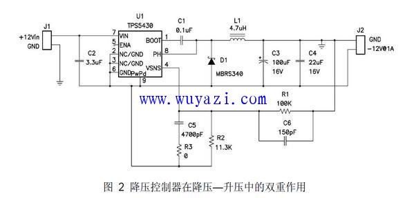
A typical capacitor layout is between +Vin and Gnd, as opposed to this. This input capacitor configuration reduces the rms current of the output capacitor. However, since the input capacitor is connected to "Vout," a capacitive divider is formed on Vout. This creates a positive peak at the output of the turn-on time before the controller begins to function. To minimize this effect, the best approach is usually to use a much smaller input capacitor than the output capacitor, see the circuit shown in Figure 2. The input capacitor current alternates between providing a dc output current and absorbing an average input current. The rms current level is the worst at the low input voltage of the highest input current. Therefore, pay more attention when selecting capacitors, and do not let their ESR be too high. Ceramic or polymer capacitors are often the preferred choice for this topology. 
It is necessary to select a controller that can be powered down with the minimum input voltage minus the diode drop and must be able to withstand the voltage of Vin plus Vout during operation. FETs and diodes must also have ratings that are suitable for this voltage range. The output voltage is regulated by a feedback resistor connected to the output ground because the controller uses the negative output voltage as the reference voltage. By carefully selecting the values ​​of a small number of components and changing the circuit slightly, the buck controller can play a dual role in the negative output buck-boost topology.
Thermal Cutout,Capillary Type Thermostat,Freezer Used Thermostat,Adjustable Thermostat
Foshan City Jiulong Machine Co., Ltd , https://www.jlthermostat.com