The servo can be used as an AC or DC motor. Early general servo DC motors, because only the type of control of large currents was passed through the sequence for many years. As transistors become capable of controlling large currents and switching large currents at higher frequencies, AC servo motors become more frequently used. Early servos were designed for servo amplifiers. Today, one type of motor design application is raised, possibly using a servo amplifier or a variable frequency controller, which means that the motor can be used in a servo system in one application and using a variable frequency drive in another application. Some companies also require any closed loop system that does not use a stepper motor servo system, so it is possible that a simple AC induction motor is connected to a speed controller called a servo motor.
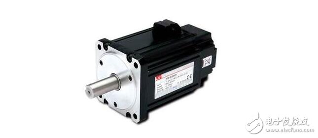
A servo motor is an engine that controls the operation of a mechanical component in a servo system, and is an auxiliary motor indirect transmission. The servo motor can control the speed and position accuracy very accurately, and can convert the voltage signal into torque and speed to drive the control object. The servo motor rotor speed is controlled by the input signal and can react quickly. It is used as an actuator in the automatic control system, and has the characteristics of small electromechanical time constant, high linearity, and starting voltage, which can receive the received electrical signal. Converted to an angular displacement or angular velocity output on the motor shaft. Divided into two major categories of DC and AC servo motor, its main feature is that when the signal voltage is zero, there is no rotation phenomenon, and the rotation speed decreases uniformly with the increase of torque.
Accurately speaking, a servo motor is a digitally controlled motor that converts electrical energy into mechanical energy for position control. The displacement is controlled by the number of pulse signals, which are controlled by the pulse frequency. The servo motor is a closed-loop controlled motor. The encoder signal of the motor's rotating shaft must be acquired to achieve control. Contrary to this, it is a stepper motor that enables open loop control. Usually the servo motor does not say "capacity" but power. Its power can be made very small, and it can be done very large, even tens or hundreds of kilowatts.
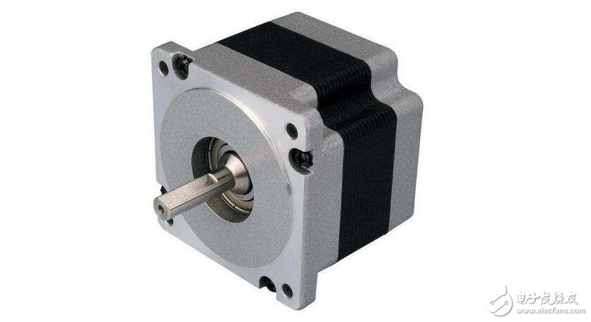
Servo System (Servo System) is a servo system. It is an automatic control system that uses mechanical position or angle as the control object, such as CNC lathes. The drive motor used in the servo system is required to have fast response speed, accurate positioning, and moment of inertia (the servo motor used in the motor system has a large moment of inertia, in order to be directly connected to mechanical parts such as a lead screw. The servo motor has a special type. Small inertia motors, in order to obtain extremely high response speed, but these motors have low overload capability and must be accelerated and decelerated when used in a feed servo system. The moment of inertia reflects the acceleration characteristics of the system when selecting a servo motor. The system's moment of inertia cannot be greater than three times the motor's number of revolutions. This type of special motor is called a servo motor. Of course, its basic working principle is no different from ordinary AC/DC motors. The dedicated drive unit of this type of motor is called a servo drive unit, sometimes referred to as a servo, and generally includes a current, speed, or position closed loop.
Servo system: An automatic control system that allows an output control amount such as the position, orientation, and state of an object to follow an arbitrary change of the input target (or a given value). The main task of the servo is to control the power, such as amplification, transformation and regulation according to the requirements of the control command, so that the torque, speed and position control of the drive device are very flexible and convenient. Servo motor working principle: Servo motor, also known as actuator motor, is used as an actuator in the automatic control system to convert the received electrical signal into angular displacement or angular velocity output on the motor shaft. Its main feature is that when the signal voltage is zero, there is no rotation phenomenon, and the rotation speed decreases uniformly with the increase of the torque.
The servo motor is a typical closed-loop feedback system. The reduction gear set is driven by a motor. The terminal (output) drives a linear proportional potentiometer for position detection. The potentiometer converts the corner coordinate into a proportional voltage feedback to the control circuit board. The control circuit board compares it with the input control pulse signal to generate a correction pulse, and drives the motor to rotate in the forward or reverse direction, so that the output position of the gear set coincides with the expected value, so that the correction pulse tends to be 0, thereby achieving the servo The purpose of precise motor positioning. The rotor inside the servo motor is a permanent magnet. The U/V/W three-phase electric motor controlled by the driver forms an electromagnetic field. The rotor rotates under the action of the magnetic field. At the same time, the encoder feedback signal from the motor is supplied to the driver. The driver according to the feedback value and target. The values ​​are compared to adjust the angle at which the rotor rotates. The accuracy of the servo motor is determined by the accuracy (number of lines) of the encoder.
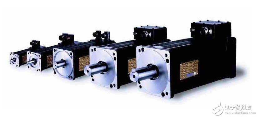
The configuration of the AC servo motor stator is basically similar to that of a capacitive split phase single phase asynchronous motor. The stator is provided with two windings with a position difference of 90°, one is the field winding Rf, which is always connected to the AC voltage Uf; the other is the control winding L, which is connected to the control signal voltage Uc. Therefore, the AC servo motor is also called two servo motors.
The rotor of the AC servo motor is usually made into a squirrel cage type, but in order to make the servo motor have a wide speed range, linear mechanical characteristics, no "rotation" phenomenon and fast response performance, it should have a comparison with a normal motor. Two characteristics of large rotor resistance and small moment of inertia. At present, there are two types of rotor structures that are widely used: one is a squirrel-cage rotor made of a high-resistivity conductive material made of a high-resistivity conductive material, and the rotor is made slender in order to reduce the moment of inertia of the rotor; One is a hollow cup rotor made of aluminum alloy, the cup wall is very thin, only 0.2-0.3 mm. In order to reduce the magnetic resistance of the magnetic circuit, a fixed inner stator is placed in the hollow cup rotor. The hollow cup rotor is widely used because of its small moment of inertia, rapid response, and smooth operation.
When there is no control voltage in the AC servo motor, only the pulsating magnetic field generated by the field winding is present in the stator, and the rotor is stationary. When there is a control voltage, a rotating magnetic field is generated in the stator, and the rotor rotates in the direction of the rotating magnetic field. When the load is constant, the rotational speed of the motor varies with the magnitude of the control voltage. When the phase of the control voltage is opposite, the servo motor Will reverse.
How to use the servo motorThe rotor of the AC servo motor is usually made into a squirrel-cage type, but in order to make the servo motor have a wide speed range, linear mechanical characteristics, no "rotation" phenomenon and fast response performance, it should have compared with the ordinary motor. Two characteristics of large rotor resistance and small moment of inertia.
At present, there are two types of rotor structures that are widely used: one is a squirrel-cage rotor made of a high-resistivity conductive material made of a high-resistivity conductive material, and the rotor is made slender in order to reduce the moment of inertia of the rotor; One is a hollow cup rotor made of aluminum alloy, the cup wall is very thin, only 0.2-0.3 mm. In order to reduce the magnetic resistance of the magnetic circuit, a fixed inner stator is placed in the hollow cup rotor. The hollow cup rotor is widely used because of its small moment of inertia, rapid response, and smooth operation.
1, wiring
Power off the control card and connect the signal cable between the control card and the servo. The following lines must be connected: the analog output line of the control card, the enable signal line, and the encoder signal line for the servo output. After reviewing the wiring without errors, the motor and control card (and PC) are powered up. At this point, the motor should not move, and it can be easily rotated with an external force. If not, check the setting and wiring of the enable signal. Rotate the motor with an external force to check whether the control card can correctly detect the change of the motor position, otherwise check the wiring and setting of the encoder signal.
2, test direction
For a closed-loop control system, if the direction of the feedback signal is incorrect, the consequences must be catastrophic. The servo enable signal is turned on by the control card. This is the servo should be rotated at a lower speed, which is the legendary "zero drift". On the general control card, there will be commands or parameters that suppress zero drift. Use this command or parameter to see if the motor speed and direction can be controlled by this command (parameter). If it is not possible to control, check the parameter settings of the analog wiring and control mode. Confirm that a positive number is given, the motor rotates forward, and the encoder count increases; given a negative number, the motor reverses and the encoder count decreases. Do not use this method if the motor has a load and the stroke is limited. Do not give excessive voltage to the test. It is recommended to be below 1V. If the directions are inconsistent, you can modify the parameters on the control card or motor to make them consistent.
3, suppress zero drift
In the closed-loop control process, the existence of zero drift will have a certain influence on the control effect, and it is best to suppress it. Use the control card or servo to suppress the parameters of zero drift, carefully adjust to make the motor speed approach zero. Since the zero drift itself has a certain randomness, it is not necessary to require the motor speed to be absolutely zero.
The servo motor itself has the function of emitting pulses, so every time the servo motor rotates by one angle, a corresponding number of pulses will be emitted, so that the pulse received by the servo motor forms an echo, or a closed loop, so that the system knows that it has been sent. How many pulses are given to the servo motor, and how many pulses are returned at the same time, so that the rotation of the motor can be controlled very accurately, so that accurate positioning can be achieved, which can reach 0.001 mm.
DC servo motors are divided into brushed and brushless motors. The brush motor has low cost, simple structure, large starting torque, wide speed regulation range, easy control, maintenance, but inconvenient maintenance (replacement of carbon brushes), electromagnetic interference, and environmental requirements. It can therefore be used in cost-sensitive general industrial and residential applications.
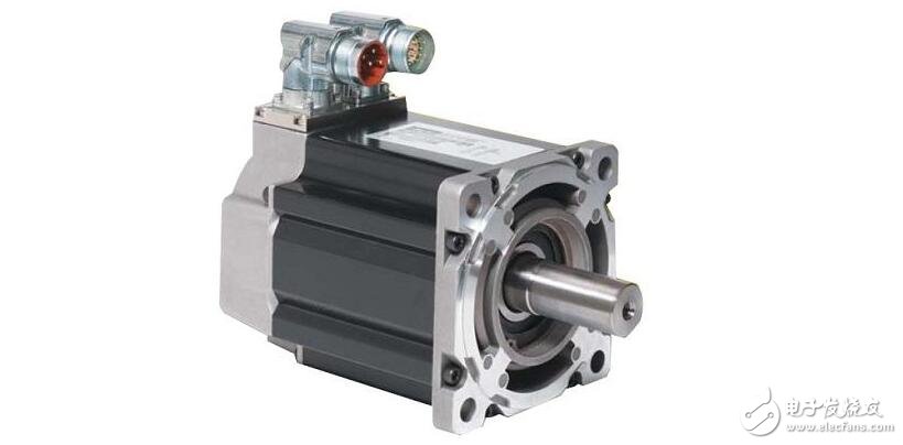
The application of servo motors is more and more extensive, although the quality is getting better and better, but if you do not pay attention to maintenance and maintenance in daily use, even the best products can not withstand the toss. Below we briefly summarize the use of the servo motor:
1. Servo motor maintenance and maintenance
(1) Although the servo motor has a high degree of protection, it can be used in places where dust, moisture or oil droplets are attacked, but it does not mean that you can immerse it in water. Try to put it in relative position. In a clean environment.
(2) If the servo motor is connected to a reduction gear, the oil seal should be applied when using the servo motor to prevent the oil of the reduction gear from entering the servo motor.
(3) Regularly check the servo motor to ensure that there is no fatal damage on the outside;
(4) Regularly check the fixed parts of the servo motor to ensure a firm connection;
(5) Regularly check the output shaft of the servo motor to ensure smooth rotation;
(6) Regularly check the encoder cable of the servo motor and the power connector of the servo motor to confirm that the connection is secure;
(7) Regularly check whether the cooling fan of the servo motor rotates normally;
(8) Clean the dust and oil on the servo motor in time to ensure that the servo motor is in a normal state;
2, protect the servo motor cable
(1) Ensure that the cable is not subjected to moments or vertical loads due to external bending forces or its own weight, especially at the cable exit or at the joint.
(2) In the case of servo motor movement, the cable should be securely fixed to a stationary part (relative to the motor), and it should be extended with an additional cable installed in the cable support so that the bending stress can be reduced The smallest.
(3) The elbow radius of the cable is as large as possible.
(4) Do not immerse the cable of the servo motor in oil or water.
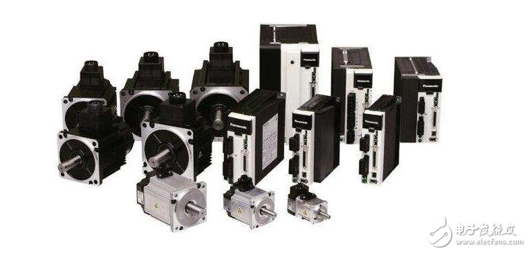
3. Determine the shaft end load allowed by the servo motor
(1) Ensure that the radial and axial loads applied to the servo motor shaft during installation and operation are controlled within the specified values ​​for each model.
(2) Take extra care when installing a rigid coupling, especially excessive bending load may cause damage or wear of the shaft end and bearing.
(3) It is best to use a flexible coupling so that the radial load is lower than the allowable value. This material is designed for high mechanical strength servo motors.
(4) For the allowable shaft load, refer to the instruction manual.
4, servo motor installation precautions
(1) When attaching/detaching the coupling part to the shaft end of the servo motor, do not hit the shaft end directly with a hammer. (If the hammer hits the shaft end directly, it will cause the encoder at the other end of the servo motor shaft to be broken)
(2) Try to align the shaft end to the optimum state (otherwise it may cause vibration or bearing damage).
Single Phase Ac Motor,Ac Single Pole Motors,Single Phase Motor,Single Phase Motor Connection
Changzhou Sherry International Trading Co., Ltd. , https://www.sherry-motor.com