Since the 20th century, China's coal mines have begun to use a large number of 127V lighting power supplies and their comprehensive protection devices. So far, the lighting equipment selected by coal mines in China is still dominated by traditional power sources. The power frequency transformers, combination switches and integrated protection devices are combined together and installed in an explosion-proof enclosure to supply power to underground coal mine equipment. As the scale of underground mining increases, the roadway and fully mechanized mining face lengthen, and the underground Power Supply voltage increases. In recent years, power supplies with large capacity of 6kVA, 8kVA or even 10kVA have appeared. However, most of these power supplies are mainly designed with power frequency transformers. They are large in size, high in quality, and low in efficiency. They cause relatively serious energy loss in the process of changing the voltage of 660V to 127V.
The use of power electronic transformers for voltage regulation has been rapidly developed in recent years. Its main performances include: no grid pollution; stable output voltage; adjustable power factor; high controllability; reliable circuit detection and protection. Therefore, research volume The replacement of power frequency transformers with small, small-quality, high-efficiency power electronic transformers has become a major research topic at this stage.
2 The design idea of ​​adopting power electronic transformer AC voltage regulating power electronic transformer is derived from AC/AC conversion circuit with high frequency link. The utility model relates to a conversion device which comprises a power electronic converter and realizes magnetic coupling by a high-frequency transformer. The outstanding feature is that real-time control of the voltage amplitude and phase of the AC side is realized by the converter, and the original secondary voltage of the transformer can be realized. Flexible adjustment of current and power. There are two main implementation schemes for power electronic transformers: one is AC/AC conversion without DC link in the transformation; the other is AC/DC/DC/AC conversion with DC link in the transformation. The main circuit structure diagram of the second scheme is shown in Figure 1. 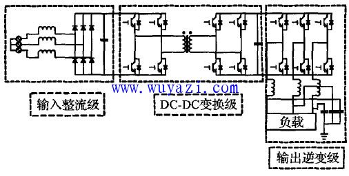
Fig.1 Main circuit structure of power electronic transformerFig.3 An AC/DC converter can be seen from Fig. 1. The power electronic transformer is mainly divided into three modules: input rectification stage, DC-DC conversion stage and output inverter stage. Based on modern power electronics technology, using the appropriate method to control the switch tube in the figure, the device can achieve the same function as the traditional power frequency transformer. Compared with the two, when the transmission power is constant, the power electronic transformer is not only much smaller in volume and quality than the power frequency transformer, but its performance is better than that of the power frequency transformer.
However, power electronic transformers based on traditional rectification and inverter methods have two major drawbacks: First, for high-power, high-voltage circuits, the voltage resistance of the switching tubes is limited; second, the rectifiers and inverters are used too. More switching tubes reduce the stability of the circuit operation, increase the energy loss, and increase the circuit cost. Therefore, for the AC/DC rectification part of the front end of power electronic transformers, a single-stage high-frequency isolated three-phase AC/DC converter is presented, and it is theoretically proved that it is used in coal mines without power frequency transformers. The feasibility of lighting power supply design. The specific structure is shown in FIG. 2, which can replace the input rectification stage and the DC/DC conversion stage in the dotted line frame in FIG. It can be seen from the comparison between Fig. 1 and Fig. 2 that the structure uses only three switching tubes in the process of implementing AC/DC. The reduction of the use of the switching device can simplify the circuit structure and reduce the circuit loss; the input end adopts the PWM rectification method. The power factor is adjustable and high power factor operation can be realized; the DC/DC link is based on the forward and reverse excitation circuit design, which can stabilize the output voltage.
The working principle of the single-stage high-frequency isolated three-phase AC/DC converter is as follows: a PWM rectification method is adopted at the input rectification end to generate a PWM square wave at both ends of the transformer primary side Np; the primary side power passes through the secondary side coil N5 Passed to the load, Lo and Dd form a freewheeling circuit to ensure the stability of the load voltage; the secondary side coil Nd and diode Dd of the transformer and the circuit composed of the load are used to demagnetize the transformer. This allows the converter to operate in both load current continuous (CCM) and input current interrupt (DCM) modes, which can achieve the above various excellent performance. 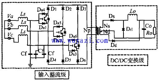
Figure 2 Single-stage AC/DC converter topology The specific control method is to adjust the input voltage and current (power factor) and output voltage by sampling the input current and output voltage for coordinate transformation and closed-loop regulation. . The commonly used three-phase PWM rectification method is as described in the above, the specific PWM rectification method in the circuit is: first define three two-level modulation variables ma(t), mb(t), mac(t) as follows, and then pass the matrix The transformation produces three-level variables ya(t), yb(t), yc(t), and the three switches are turned on and off by the state of these three variables. The specific relationship is as follows:
The switch control table obtained by the above two equations is shown in Table 1. 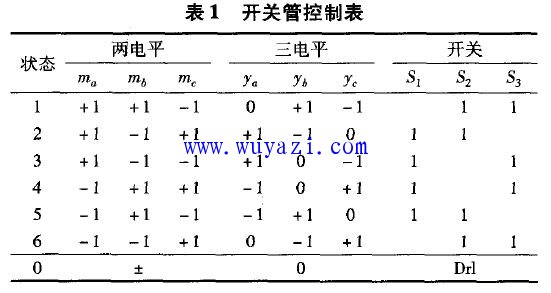
It is obtained from the control table: when the state of the three variables is 0 level, the corresponding switch tube is turned off; and when the state is non-zero state, the corresponding switch tube is turned on. Thus, the PWM waveform generated by using ya(t), yb(t), yc(t) can be used to drive the switching of the switching tube to control the normal operation of the rectifier circuit of the previous stage.
The DC/DC link using the high-frequency transformer can be equivalent to a one-way Buck converter. The equivalent circuit structure is shown in Figure 3. The operating state of the circuit can be simplified as described in three stages: â‘ switch is closed, the transformer core is magnetized, the power delivered to the load from the DC Power Source E through the secondary coil N; â‘¡ switch is turned off, the current in the inductor through the diode Dd Lo After the freewheeling, the transformer core begins to demagnetize through the demagnetization current generated by the demagnetization winding Nd through the load circuit; 3 the switch is still open, the demagnetization has been completed, but the inductance Lo still continues to flow through the Dd. 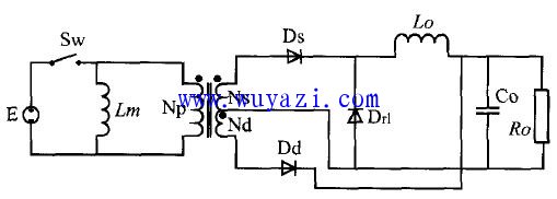
Figure 3 DC/DC link equivalent circuit This circuit is designed based on the forward and reverse excitation circuit. The proper design method and parameters can ensure the continuity of the load current and the discontinuity of the primary inductance. Only in this way can the three be guaranteed. The working state is running normally.
4 Circuit Simulation and Analysis In order to verify the effectiveness of the circuit, the simulation is based on the circuit. The main parameters are: phase input line voltage 660V; switching frequency 20kHz; output voltage is 225V, which can provide 127V AC for inverter output. Stable DC power supply.
The input inductance and capacitance values ​​are 175μH and 23μH, Np=28, Ns=12, Nd=3, and the output inductance and capacitance are 130μH and 1000μF, respectively. The waveform of the input voltage and input current and the waveform of the output voltage are shown in Fig. 4. 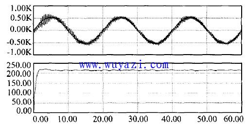
Figure 4 Simulation input voltage and current and output voltage waveform The input current is amplified by 10 times to obtain the waveform of input voltage and input current in Figure 4. It can be seen that the waveform of voltage and current is basically consistent in phase, and the input power at this time The factor is higher. The above purpose is achieved by generating a corresponding PWM waveform through the closed loop adjustment control and controlling the opening and closing of the corresponding switching tube.
The simulation results show that the circuit topology can theoretically realize the input rectifier rectification stage and the D/DC conversion stage of the isolation part required for the underground coal mine lighting power supply, which is simpler than the corresponding structure in the traditional power electronic transformer. easy to accomplish.
5 Conclusion This article describes a three-phase AC/DC converter. This circuit topology uses only three switching tubes, which greatly simplifies the structure of the circuit, makes it easier to implement, and can be flexibly applied to the design of power frequency transformerless power supply in coal mines. The circuit adopts PWM rectification method, and the input terminal has high power factor, and can realize unit power factor operation; the output voltage is stable, the adjustment is convenient, the action is reliable, and the performance is good. The development of modern power electronics technology provides theoretical and technical basis for the research of coal-free power frequency transformer power supply. This paper only proposes a new circuit structure for related technical solutions. With the continuous advancement of power electronics technology, power electronics are adopted. The technically constituted coal mine underground power frequency transformer power supply will be widely promoted and applied.
Guangzhou Ruihong Electronic Technology CO.,Ltd , https://www.callegame.com