The oscilloscope's track and trend features add two mathematical measurement functions that can be used to gain insight into the meaning of the measurement data. The trend is a numerical sequential display of the measured parameters, taking the number of events as a horizontal value. Tracking is a plot of measured parameter values ​​versus time. These two functions allow the oscilloscope to perform the following tasks: data recording, detection of functional relationships between measurements, identification of abnormal conditions in long data records, and even demodulation of angle modulation or pulse width modulation signals.
Regardless of trend or tracking, based on oscilloscope measurement parameters, most oscilloscopes can provide about 25 measurement parameters, including frequency, amplitude, and rise/fall times. The oscilloscope keeps track of these measurements and uses them to display statistics of the values ​​of the parameters, which of course can also be plotted as trends and/or traces.
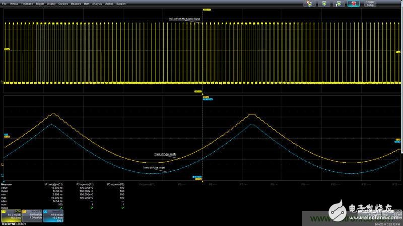
Figure 1 shows an example of how to use the trend or trace function. The acquired trace (shown in yellow in the upper grid) is a pulse width modulation (PWM) signal. The parameter P1 measures the pulse width on the acquired waveform cycle by cycle. The parameter statistics include the pulse width minimum (2.698 ns) and maximum (49.3 ns) pulse widths, as well as the mean and standard deviation of all measurements. The acquired waveform has 100 cycles (100k samples), and the pulse width of each cycle is recorded in the statistical data report.
The bottom trace (blue) is the trend of pulse width measurement. It contains these 100 pulse width measurements, arranged in the order being tested. Each point on the trace represents a value. The number of values ​​in a trend graph is usually user-selectable and is generally measured in 1-2-5 steps, from 2 to 1,000,000 optional. In this case, the trend and source waveforms are synchronized because the length of the trend plot for 100 values ​​matches the number of cycles for the source waveform, but this is not always the case.

Figure 1: Pulse Width Trending and Tracking from Pulse Width Modulation Waveforms
The center trace (orange) is the trace of the pulse width. This waveform contains the same 100k points as the acquired waveform. Each measured value is upsampled (upsampling rate) to match the duration of each cycle of the source waveform. The trace pattern is always synchronized with the source waveform.
Since the tracking function has a time synchronization feature, it can be used to demodulate the PWM waveform signal. By tracking the parameter frequency, it is also possible to use it to demodulate a frequency-modulated (FM) or phase-modulated (PM) signal.
data record
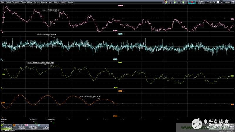
The trend function is ideal for data logging. Let's take a look at the measurement data in Figure 2.

Figure 2: Data logging example shows changes in RMS line voltage and room temperature. A trigger hold-off is used to read every 5 seconds.
The top trace is the trend of the RMS line voltage. Hysteresis is used to insert a 5s delay between each measurement. The second trace at the top is the thermocouple output trend. Math trace F4 (third trace at the top) filters the thermocouple output and rescales it in degrees Celsius. The entire chart records 2000 measurements at intervals of 5 seconds and a duration of 2.7 hours.
When the air conditioning system is turned on, the line voltage drops, and then the temperature drops slightly. The whole process shows cyclical changes. This can be verified by cross-correlating the original trend waveform, which is shown in the bottom trace. The periodicity is clearly shown in related functions, approximately every 252 measurements or once every 20 minutes.
Use tracking for demodulation
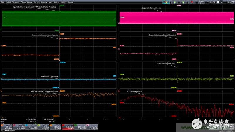
In some applications, demodulating the angle modulated signal is helpful. For example, when measuring the frequency response of a phase-locked loop (PLL), you can use the trace function to see the phase changes at the input and output of the PLL. Figure 3 shows the PLL frequency response measurement.

Figure 3: Demodulation of the phase modulation input using time interval error tracking and output to the PLL.
The frequency response of any device can be measured by using a step function stimulus that is differentiated and subjected to a Fast Fourier Transform (FFT). In Figure 3, the top-left trace is the PLL input: a 66.67 MHz sine wave with a 2 radius phase step at the midpoint of the waveform. Measurement parameter P1 measures the time interval error (TIE) of the waveform. The TIE measures the time difference between the measured position of a waveform edge or a threshold crossing and the ideal position of that edge. TIE is essentially the instantaneous phase of the signal. The second trace from the top left side of Figure 3 shows the TIE trace of the PLL input. TIE tracking demodulates the phase modulation input. The phase step at the center of the input waveform is obvious.
The upper right trace is the output of the PLL. Measure the TIE of the PLL output and use tracking to demodulate the phase. You can see the effect of the PLL on the phase step. See the second trace at the top of the right side of Figure 3. The tracking function can see the phase changes of the PLL input and output, providing a view of the phase changes that are not apparent in the source trace, which is important because the PLL is a phase sensitive device.
Pulse functions are often used as input signals to measure the frequency response of the signal. Differential This step response produces an impulse response. The third set of traces shows the demodulated PLL input and output signals, respectively, on the left and right sides of Figure 3, respectively.
The bottom left trace in Figure 3 shows the FFT's impulse response FFT. Please note that this is a basically flat response. In the lower right trace, the PLL output impulse response FFT shows the frequency response of the PLL. Technically speaking, the frequency response is the complex ratio of the output to the input FFT, but since the input is spectrally flat, the output spectrum is close to the frequency response of the PLL.
Trend or tracking?
Trends are the best choice for data records. The trend trace contains only one point for each measurement, so storage efficiency is high. Tracking is necessary if time-related operations (such as FFT or filtering of the traces) need to be performed. Tracking can also be useful if tracebacks of anomalous measurements are intended to be traced back to the source trace because the traces are synchronized with the source traces. The cost of tracking this work is to use more samples in the function.
The trend and tracking function allows you to view the history of a single parameter measurement. By performing a series of measurements on the waveform, you can use the oscilloscope's math and analysis tools to gain insight into the process under test, which can greatly reduce troubleshooting and debugging time.
Flat Wire High Current Inductor
Flat Wire High Current Inductor,Small Flat Wire Common Mode Inductors,High Current Flat Wire Inductors,High Power Flat Wire Inductors
Shenzhen Sichuangge Magneto-electric Co. , Ltd , https://www.scginductor.com