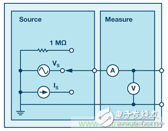
The ADALM1000 is essentially a signal source measurement unit, but it can also be viewed as a stand-alone oscilloscope and function generator. However, when viewed separately, since the output function (generator) and the input function (oscilloscope) share one pin, only one function can be used at a time.

Figure 1. Block diagram of an ADALM1000 SMU channel.
Why is the programmable signal source measurement unit important?For some types of testing, programmable instruments may not be important. You may only want to read it once or a small number of times. But in many cases, you might need to collect a lot of data to generate a curve or chart of performance over time. However, manual operation can be time consuming and error prone.
There are also a number of different experiments that require automated data collection to obtain faster or more accurate measurements, or to obtain measurements on long-term scales (months or even years). At this point, you definitely need a computer to collect the data and export it to the database for analysis.
Why do you need a negative voltage?Not all experiments require a negative voltage, and in some cases you can avoid it. However, many different types of devices work differently if a positive or negative voltage is applied. To fully understand how these devices work, we need to be able to change the sign of the applied voltage. Each SMU channel in the ADALM1000 can only generate voltages from 0 V to 5 V (relative to ground). It provides fixed 2.5 V and 5 V outputs that can sink current as well as sink current. The DUT can be connected between the 2.5 V output and the SMU output instead of ground to sweep the DUT voltage from –2.5 V to +2.5 V. In addition, since the ADALM1000 has two SMUs, the DUT can be connected between two SMU outputs. One channel scans from 0 V to 5 V, the other channel sweeps from 5 V to 0 V, and the voltage across the DUT is from –5 V to +5 V.
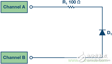
For example, consider a diode—a device that only allows current to pass in one direction. In order to evaluate whether the diode is working properly, we need to see if the current in both directions can pass through it. There are two ways to check. We can measure the diode in one direction, turn it manually, measure the other direction, and then combine the data together. However, if we apply positive and negative voltages, then we only need to measure the current. In fact, this technique is very useful and is often used to characterize many devices with diode-like behavior. Solar cells and LEDs are good examples. Figure 2 shows how to connect a diode to the ADALM1000 to scan –5 V to +5 V.

Figure 2. Scanning diodes from –5 V to +5 V.
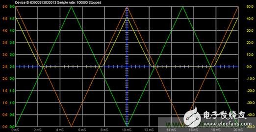
Channel A is programmed to sweep from 0 V to 5 V, while Channel B is programmed to sweep from 5 V to 0 V. The difference between the channels appears across the resistor to limit current and diode. The time domain waveform is shown in Figure 3. The green curve is the channel A voltage, the orange curve is the channel B voltage, and the yellow curve is the channel B current (the channel A current is not shown, which is the opposite of the channel B current).

Figure 3. Voltage and current waveform versus time.
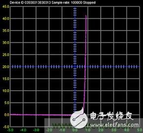
We can compare these measurements to each other to make a graph and perform some simple mathematical calculations at the same time. What we want to draw is the relationship between the current through the diode and the voltage across the diode. To calculate the voltage across the diode, we can subtract the voltage drop across the resistor from the difference in voltage between channel A and channel B (V = I&TImes; R). The following Python equation (used in ALICE) can perform this calculation:
Where 100 is the value of the resistor. The relationship between the diode current and the equation is shown in Figure 4.

Figure 4. Diode current vs. –5 V to +5 V voltage.
Braided Sleeve,Braided Cable Sleeve,Expandable Braided Sleeving,Braided Wire Sleeve
Shenzhen Huiyunhai Tech.Co., Ltd. , https://www.cablesleevefactory.com