1. Basic principles of radio frequency identification
A typical radio frequency identification system consists of a transponder, a reader, and a data exchange and management system. The basic working principle of the system is that the reader read and write terminals continuously emit a set of electromagnetic signals at a fixed frequency (generally 134.2 kHz), so that when an LC series resonant circuit in the contactless card (transponder) chip enters When the reader reads and writes the working area of ​​the terminal, and its working frequency is the same as the frequency of the signal sent by the reading and writing terminal, the LC resonant circuit generates resonance under the excitation of the electromagnetic wave. Resonance causes the capacitor in the card to have a charge. At this point, a single-pass electronic pump connected to the other end of the capacitor can transfer the charge in the capacitor to another capacitor and store it. When the accumulated charge voltage reaches 2V, this voltage can be used as the operating power of the transponder. At this point, the transponder responds to the reader's request and modulates the information and issues it for reading by the reader. The E2PROM in the transponder is used to store the ID number of its unique electronic tag (code length is 64 bits) and other user data.
This article refers to the address: http://
2, radio frequency identification car burglar alarm design
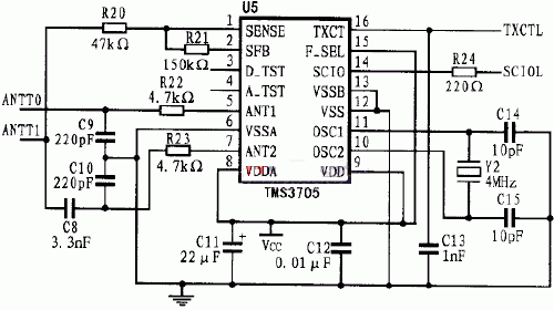
The radio frequency identification system developed in this paper is the TMS3705 of Texas Instruments, which is a radio frequency signal reading and writing chip, and uses the company's RI-TRP-RR2B (read-only type) as a transponder. The communication between the base station chip and the microprocessor (MCU) in this design requires only two general-purpose I/0 lines, which is very convenient to use. The modulation and demodulation circuit is shown in Figure 1.

Figure 1 modulation and demodulation circuit
The signal transmitted by the transponder is received by the reader antenna, processed by the base station, and sent to the I/O port of the microprocessor. The FSK (Frequency Shift Keyed) signal is sent to the reader. The reader is only responsible for the demodulation of the signal, and the decoding of the signal is performed by the microprocessor. The microprocessor can perform decoding operations based on the high and low durations of the input signal.
2.1 Data Storage Format in RI-TRP-RR2B RF Card
There are 14 bytes of data in the RI-TRP-RR2B transponder, and the order of storage is as listed in Table 1. The user data area has a total of 10 bytes, of which the 2nd to 9th bytes are the user 64-bit id area, and the 10th and 11th bytes are the CRC check code.
Table 1 Data in RI-TRP-RR2B 
2.2 Car alarm based on radio frequency identification technology

Figure 2 Radio frequency identification system hardware block diagram
The system is based on ATMEL's AT89C51 microcontroller, and its hardware composition is shown in Figure 2. The system consists of a radio frequency identification device, an external memory, a voice circuit, a clock circuit, a power management circuit, a watchdog, and a detection control circuit. This system is highly compatible and can be used with other anti-theft devices. It is a cost-effective car anti-theft device. The main features of the anti-theft alarm system are as follows:
(1) Ordinary car alarms mainly use the keyboard input method to identify the driver's identity. This method brings a lot of inconvenience to driving, and because of its limited password combination, it is easier to be stolen and deciphered. The use of radio frequency identification technology to identify identity can effectively solve this problem. The owner only needs to carry the transponder (32mm) close to the reader's induction coil (into the sensing range of about 7cm), the identification can be completed in an instant, and the password is not decipherable, thus greatly improving the anti-theft effect. If the original transponder is lost, then the user only needs to press the "learn" button, and then the standby transponder is close to the sensing antenna to complete the ID learning, the original ID will be automatically cleared, and the lost response will be The device fails and the alternate transponder takes effect.
(2) Its external memory uses ATMEL's AT24C01 serial E2PROM. The AT24C01 is a 1K-bit electrically erasable memory with an I2C bus that can be used to store the owner's ID and the logo information of the microcontroller before the sudden power loss. Since it is a non-volatile memory, the information it stores is not lost after power-down. After the power is turned back on, the system will return to the state before the power failure, which can effectively prevent the damage of the vehicle power and improve the safety.
(3) The voice circuit is based on the ISD1420 integrated voice chip. Combined with the conditioning and power amplifier circuit, multi-segment voice recording and playback can be realized, and the sound quality is good. The circuit can conveniently realize the safety prompt and alarm function of the anti-theft system.
(4) The power management circuit and the watchdog circuit are implemented using the MAX705. The chip combines power management with a watchdog function. The combination of power management and single-chip software can be used to protect data from sudden power failure, so that the MCU saves the state information immediately before power-off to the E2PROM, so that it can be read when power is restored. The watchdog circuit can effectively monitor the MCU to prevent various interferences on the car and cause the MCU to enter an infinite loop, thereby improving the stability and reliability of the whole machine.
(5) The detection control circuit is used to detect various status information of the car for the decision of the MCU. These include the detection of the door, the detection of the power supply, the detection of the brake signal and the detection of the keys. The control circuit includes the control of the directional light, the control of the power supply, the control of the central locking and the control of the hub lock.
3. Software design of radio frequency identification system
The core of the software design of the RFID system is to read and verify the signals from the RF card. The flow chart of the identification subroutine is shown in Figure 3. The radio frequency card used in this system is a read-only card, so it is only necessary to read out its unique 64-bit ID, and then compare it with the existing ID in the E2PROM after verification, and then determine the identity of the owner.

Figure 3 Identification subsystem flow chart
3.1 Reading of RF signals
Figure 4 shows the format of each byte of the signal, which consists of 10 bits. The first bit is the start bit, fixed to 1, the last bit is the stop bit, fixed to 0, the second to the 9th bit is the actual transmitted data (the first received bit is LSB), because it is negative logic, so The data needs to be inverted.

Figure 4 1 byte transmission format
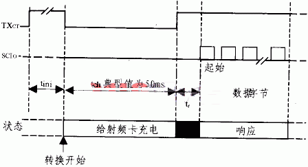
Figure 5 shows the timing of the reader reading data. The data sent by the RF card is modulated by FSK. TXCT can be set to 0 during operation, delayed by 50ms, and then restored to 1 by TXCT. After about 3ms, SCUO began to output data. The first byte of the data is the start byte, which outputs a total of 14 bytes of data.

Figure 5 RF signal reading control
3.2 CRC data verification algorithm
The CRC check is set to check if the information field is correctly transmitted. It is a function of the information field. This paper uses a 16-bit cyclic redundancy check code (CRC-CCITT), which generates a polynomial of:
![]()

Figure 6 CRC check implementation principle
The CRC check code is widely used in communication because of its simple implementation and high accuracy. The CRC-CCITT used in this paper can detect all double errors, odd dislocations, burst errors with burst lengths less than 16, 99.997% burst errors with burst length of 17 and burst lengths greater than 99.998%. A burst error equal to 18. The operation of the CRC check code can be implemented by a shift register and a half adder. The specific verification principle is shown in Figure 6. The verification process at the sender is as follows:
(1) First, set the initial value of the CRC check code (2 bytes) to 00H, 00H (0 to 15 in Fig. 6 indicates bits 0 to 15 of the CRC).
(2) The CRC check code is all shifted to the right by one bit, and the X bit of the data of the data to be CRC checked is XORed at A.
(3) After the operation in step 2, the result at A is 1, then invert the MSC (bit 15), and then check if the MSB is 1, if the MSB is 1, then the inverse phase 13 and bit 10, otherwise go to the step 4. If the result at A is 0, it is checked whether the MSB is 1, and if the MSB is 1, the phase 3 and the bit 10 are reversed. If not, the process proceeds to step 4.
(4) Check if A has been operated 64 times. If not, repeat steps 2 to 4.
(5) Repeat steps 2 to 4 to do the CRC operation, and the final value obtained is the CRC check code.
The process of receiving the check at the receiving end is actually the process of adding all the information codes plus the CRC check code, and then requesting the CRC check as a whole. If the final result is all zeros, it means that the CRC check is correct, otherwise it indicates an error. .
The transponder information must be read in strict accordance with its timing, otherwise the correct information will not be obtained. Due to space limitations, the specific procedures are not listed in this article.
4 Conclusion
This paper mainly introduces the method and implementation of RFID technology applied to automobile anti-theft system. The new car anti-theft device developed by the author using radio frequency identification technology has been stable and reliable after several debugging and trials. Good results have also been achieved in practical applications. Practice shows that the anti-theft device has the advantages of advanced technology, practicality, convenience, good compatibility, small size and full function, and is an ideal car anti-theft system.
Minsound offers a great range of Driver Units,providing accurate reproduction.high intelligibility and dependable performance in commercial sound,signaling and public address loudspeaker systems.
All models are suited for Minsound reflex horns,equipped with the industry standard 1-3/8"-male tread pattern.
This series driver units are made of Neodymium magnet for good performance.
Neodymium Driver Units,Neodymium Driver,Neodymium Drivers,neodymium speaker magnets,Neodymium magnets
Taixing Minsheng Electronic Co.,Ltd. , https://www.ms-speakers.com