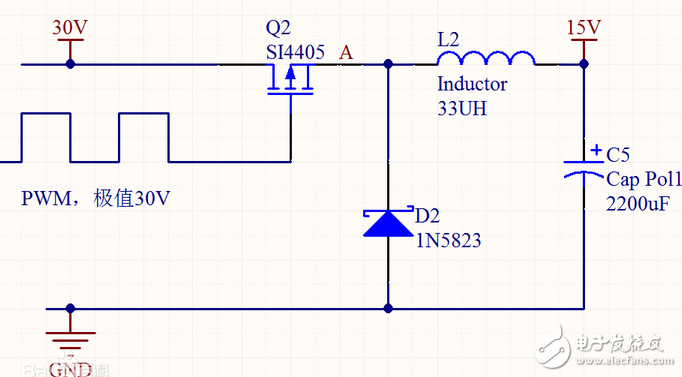
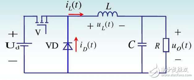
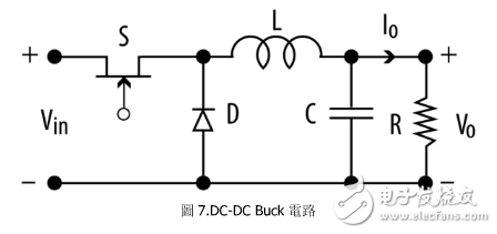
In the buck circuit, the inductor stores energy when the switch is turned on, and the load continues to flow when the switch is turned off. At the same time, it and the capacitor form a second-order filtering system to output a relatively stable voltage and current. The inductor reduces the current ripple in the BUCK circuit and reduces the capacitance value of the capacitor design.
The inductance is a magnetic component and naturally has the problem of magnetic saturation. Some applications allow inductor saturation, and some applications allow the inductor to start saturation from a certain current value, and some applications do not allow the inductor to saturate, which requires differentiation in specific lines. In most cases, the inductor operates in a "linear region" where the inductor value is a constant and does not vary with terminal voltage and current. However, buck step-down circuit has a problem that cannot be ignored, that is, the winding of the inductor will lead to two distributed parameters (or parasitic parameters), one is the unavoidable winding resistance, and the other is related to the winding process and materials. Distributed stray capacitance. Stray capacitance has little effect at low frequencies, but gradually increases with increasing frequency. When the frequency is above a certain value, the inductance may become a capacitive characteristic. If the stray capacitance is "concentrated" into a capacitor, the capacitance characteristics exhibited after a certain frequency can be seen from the equivalent circuit of the inductor.


1. Inductance and tolerance
Inductance refers to the nominal value of the inductance of the frequency measurement required by the product specification. The inductance is in units of Henry, millihenry, microhenry, and Nahen. The error is subdivided into: F (±1%); G (±2%); H (±3%); J ( ±5%); K grade (±10%); L grade (±15%); M grade (±20%); P grade (±25%); N grade (±30%); the most commonly used is J , K, M grade.
2. Rated operating current
Take the 1.25 to 1.5 times of the rated current of the inductor as the maximum working current. Generally, the user should be derated by 50%. It is safer to use. Generally, in engineering practical applications, only the saturation current of the inductor is measured, and then 80% is taken as the rated current.
3. DC resistance
Except for power inductors that do not measure DC resistance (only check the wire size), other inductors must specify the maximum DC resistance as required, generally as small as possible.
4. Test frequency
To correctly measure the L, Q, and DCR values ​​of the inductor, an alternating current must be applied to the inductor under test as specified. The closer the frequency of the current is to the actual operating frequency of the inductor, the better.
5. Stability of inductance
The ratio of the inductance ΔL/Δt and the original inductance L value of the inductor due to the change of the ambient temperature at 1 °C is the temperature system a1 of the inductor, a1=ΔL/L*Δt. In addition to the temperature coefficient of inductance to determine its stability, attention should also be paid to changes in inductance due to mechanical vibration and ageing.
6. Inductor package size
Inductor packages typically include a chip package and a plug package. If you make a clear description of the package in the bill of materials, you can reduce the chance of using the wrong material. The package form of the inductor is also a description of the shape and volume of the inductor.
Most of the inductor selection specifications are similar, generally need to pay attention to these matters, the specific needs to follow the circuit design to meet the parameter performance.

According to the inductance catalog comparison, it is convenient to find a suitable inductor. Some TIps are also given below:
1. The inductor current is selected according to the maximum output current in the design.
2. The value of the induction coefficient must reach the theoretical calculation
3. Choose the ideal DC impedance because the smaller the impedance, the smaller the DC loss.
4. Select the appropriate inductor structure and core category

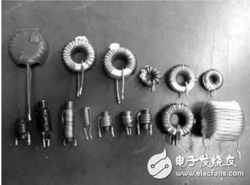
The application of the inductor in the DC-DC Buck circuit works in continuous current mode. The voltage across the inductor can be abrupt but the current does not mutate. Since the magnetic field in the inductor will generate electromagnetic radiation to the periphery and cause interference to surrounding sensitive components, shielding is the first consideration. From Figure 4, the difference between shielded and unshielded inductors can be seen. The shielding inductance is mainly due to less external radiation, but the size is relatively large, the loss of the coil is large, and the price is expensive. Unshielded inductors can be made very small, current can be made very large, and the price is also cheap. If the problem radiation is a key factor in the design, shielding inductance is still preferred. The other is that ring-shaped inductors are becoming more and more popular, and the ring shape is advantageous for electromagnetic shielding, and the gap distribution of such air is also advantageous for improving the current processing.
Backup Energy System,Home Backup Power,Backup House Power,Back Up Power System
SUZHOU DEVELPOWER ENERGY EQUIPMENT CO.,LTD , https://www.fisoph-power.com