Choosing HB LED drivers for automotive lighting applications
Abstract: This article discusses how to properly select HB LED drivers for automotive lighting applications, introduces different types of HB LED driver topologies, and gives them based on the requirements of various automotive lighting designs (including: internal lighting, external lighting, display backlight, etc.) Recommended configuration.
Compared with traditional lighting technologies, HB LEDs have several key advantages: they do not contain any harmful substances, such as mercury in CCFL; they consume lower power and have a longer lifespan. In addition, HB LED has a higher cost competitive advantage than traditional solutions, greatly reducing the overall cost of the system (for example: operation and maintenance costs).
Of course, the use of HB LEDs also faces some special challenges, especially in noisy working environments such as cars. This article discusses the basic principles of HB LED driver selection, compares different driver topologies, and provides recommended configuration solutions for different automotive lighting applications, including: car ceiling lights, daytime running lights (DRL), tail lights (RCL), fog Lights and low beam / high beam etc.
HB LED requires constant current to drive the HB LED driver circuit for managing the power supply of HB LED. It is critical that the drive circuit maintain a constant current and minimize voltage fluctuations. Excessive drive current will increase the junction temperature of HB LED and accelerate the degradation of HB LED.
In lighting applications, in order to obtain higher lumens, high-power HB LEDs need to be used. The forward conduction current of these HB LEDs is generally 350mA to more than 1A. The forward voltage of white, blue and green HB LEDs is in the range of 2.8 to 4.5V, and the forward voltage of red and amber HB LEDs is in the range of 2.3 to 3.5V.
In order to maintain a fixed color spectrum and brightness, HB LED drivers must meet specific rated current requirements. Driving a HB LED with a voltage source and limiting current in series resistors may produce unacceptable changes in brightness and spectrum. HB LED brightness adjustment The HB LED's luminous color will change with the change of current. Therefore, the effect of adjusting the fixed current using the pulse width modulation (PWM) method is better than adjusting the actual current amplitude, that is, the DC current is maintained at the HB LED The fixed value specified by the manufacturer, current chopping according to a certain frequency and duty cycle, and the use of pulse width modulation to adjust the brightness can maintain a consistent spectrum at different brightness levels. In order to avoid visual flicker, the dimming frequency should be higher than 100Hz. The dimming range depends on the minimum duty cycle allowed by the HB LED driver.
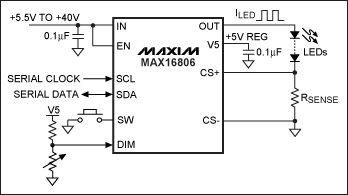
Most HB LED drivers require a microcontroller or external timer to generate brightness control signals. HB LED drivers such as the MAX16806 internally generate a PWM signal, which is modulated by an external voltage applied to the DIM input (Figure 1). This configuration can eliminate external microcontrollers or switch mode converters in applications such as automotive interior lighting.

Figure 1. The 350mA linear HB LED driver IC MAX16806 eliminates the need for a microcontroller or switch-mode converter
The best choice for automotive interior lighting-the best solution for linear drivers to drive HB LEDs is to use a constant current source. A simple circuit to achieve a constant current source is: use a MOSFET in series with the HB LED to detect the current of the HB LED and compare it with the reference voltage. The comparison signal is fed back to the operational amplifier to control the gate of the MOSFET. This circuit is like an ideal current source, which can maintain a fixed current when the forward voltage and the power supply voltage change.
The advantage of the linear driver compared to the switch mode driver is: the circuit structure is simple and easy to implement, because there is no high-frequency switch, so there is no need to consider EMI problems. In addition, the peripheral components of the linear driver are few, which can effectively reduce the overall cost of the system.
Linear HB LED driver ICs, such as the MAX16806, internally integrate MOSFETs and high-precision references, which can maintain consistent brightness for each string of LEDs (Figure 1). For example, the input voltage required by the MAX16806 only needs to be 1V higher than the total voltage drop of the HB LED. Using an external current-sense resistor to measure the current of the HB LED, the MAX16806 can guarantee a constant output current when the input voltage or the LED forward voltage changes.
The power consumption of the linear driver is equal to the HB LED current times the voltage drop of the internal (or external) series regulator. When the HB LED current or input power supply voltage increases, the power consumption also increases, which limits the application of linear drivers. Since overheating will affect the lifetime of HB LEDs-which is also a drawback of this type of light source-it is very important to limit the power consumption of the lamp.
Thankfully, the brightness of HB LEDs can be adjusted to avoid overheating. In order to reduce power consumption, the MAX16806 monitors the input voltage. If the input voltage exceeds a preset value, it will reduce the drive current of the HB LED to reduce power consumption. This function can avoid the use of switching power supplies in certain applications, such as car ceiling lights or DRL, etc. In these applications, the light is usually dimmed when abnormally high battery voltage occurs.
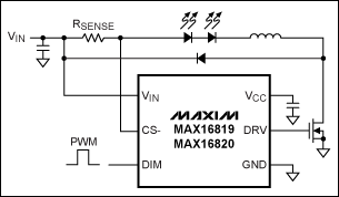
Ideal for automotive exterior lighting-switch-mode buck driver When the input voltage is much higher than the total voltage drop of the series HB LED, it is best to use a switch-mode buck conversion driver (Figure 2), which can reduce power consumption To the lowest, so as to obtain higher drive efficiency.

Figure 2. Using a switch-mode buck conversion driver to reduce power consumption and improve the driving efficiency of lighting components
Unlike general buck controllers used to drive HB LEDs, the MAX16819, MAX16820, MAX16822, and MAX16832 HB LED drivers use hysteretic control and no control loop compensation, which simplifies the design and helps reduce the number of external devices. The integrated high-voltage current detection amplifier can work at a switching frequency of up to 2MHz, effectively reducing the board space and the number of components, and can be ideally used for the front and rear lighting of automobiles (RCL, DRL, fog lights / low beam lights).
Ideal for automotive headlights—switch-mode buck-boost (SEPIC) drivers When the input voltage is above or below the total turn-on voltage of the HB LED, a buck-boost mode driver must be used. In a buck-boost configuration, a floating current-sense amplifier is needed to detect and regulate the HB LED current. In addition, additional protection, such as overvoltage protection, is required to protect the system from damage when an open or short circuit occurs in the HB LED. For high-power LEDs in automotive headlights, the input voltage may range from 5.5V (cold start) to 24V (battery voltage doubler). At this time, the ideal choice is the buck-boost circuit. The driver must also be able to withstand peak load dump voltages above 40V.
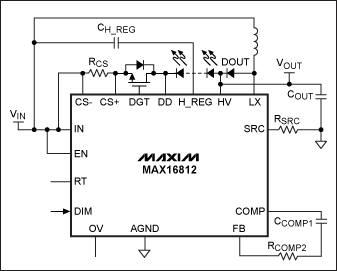
Highly integrated HB LED drivers, such as the MAX16812 or MAX16831, can help reduce the number of components and reduce costs in the design of automotive headlights. For example, the MAX16812 integrates a differential current-sense amplifier and a 0.2Ω power MOSFET rated at 76V to control the current of a single string of HB LEDs (Figure 3). In addition, the internal dimming MOSFET driver can automatically turn off the power of the LED string during load dump, enhancing the reliability of the system.

Figure 3. When the input voltage may be higher or lower than the total voltage of the series HB LED, the buck-boost driver topology should be selected
LCD backlight solution in the car-switch mode boost driver If the input voltage is always lower than the total voltage of the HB LED string, you need to use a boost converter. In the new models in 2010, head-up displays are generally added, and the boost converter is very suitable for such applications or LCD backlighting. These applications require a 3000: 1 brightness adjustment range to accommodate a wide range of ambient lighting conditions in the car. The driver must provide an additional dimming MOSFET driver to turn on / off the LED in a very short time. Dimming MOSFETs can also protect LEDs during load dump.
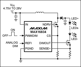
The HB LED driver circuit shown in Figure 4 is used for LCD backlighting in automobiles. The MAX16834 integrates a high-side current-sense amplifier, PWM dimming MOSFET driver, and a highly reliable protection circuit, which greatly simplifies the design of the LCD backlight circuit. This HB LED driver provides a 3000: 1 PWM dimming range with an input voltage range of 4.75V to 28V, ensuring stable operation under cold start and load dump conditions.

Figure 4. A boost driver with a wide dimming range of 3000: 1 and a built-in protection circuit can be ideal for LCD backlighting in automotive entertainment facilities.
Conclusion Reasonable selection of HB LED drivers requires understanding the requirements of specific LED lighting devices to optimize system design. The designer first needs to determine the electrical parameters, such as: input voltage, LED current, LED forward voltage, and the variation range of these parameters. Safety, EMI, thermal management, mechanical performance, and available circuit board area are also factors that must be considered.
Linear drivers are more suitable for low-cost, low-EMI applications, such as: automotive interior lighting, simple design. Switch-type drivers are suitable for applications such as high power, high efficiency, and a wide input voltage range, such as automotive exterior lighting, but the cost is high and EMI issues need to be considered.
Maxim provides a wide range of HB LED driver solutions for different applications, which can reduce the system size, reduce design complexity and cost in automotive solid-state lighting. All automotive lighting solutions can work in the temperature range of -40 ° C to + 125 ° C, and meet the requirements for short circuit protection and thermal shutdown in automotive applications.
Progressive Punching is an efficient self-riveting process of fixed rotor, which can realize large-scale and precise riveting operation and is suitable for mass manufacturing production line. The following is the introduction of progressive rotor self-riveting process:
First, determine the type and specification of the stator and rotor required for riveting, and prepare the rivets and riveting machines required for riveting. Rivet size should match the hole size of stator and rotor to ensure tight fit and firmness.
According to the size and riveting requirements of stator and rotor, the rivet is machined into the corresponding length and shape. Progressive punch riveting machine also needs to adjust, set, calibrate the position of the riveting head, pressure, speed and other parameters.
Insert the rivet into the stator hole, and start the progressive punching riveting machine with electricity. The rivet will exert force on the rivet head according to the set parameters, and form a large number of threaded processes on the inner wall of the stator hole, so that the rivet deformation is firmly connected with the stator.
Wait for the rivet deformation, riveting process is complete. The remaining rivet tail should be cut off and inspected after riveting is completed to ensure that the riveting is firm and reliable and the transmission system runs smoothly.
In general, the process of progressive impact fixed rotor self-riveting can improve the production efficiency, but also ensure the precision and stability of riveting. However, riveting machine adjustment requires specialized skills, so an operator familiar with the riveting process is required.
Motor stator riveting, beraring stator riveting, generator stator riveting
Henan Yongrong Power Co., Ltd , https://www.hnyongrongglobal.com