Cardiovascular diseases are increasingly threatening human life. Pre-discovering abnormalities and timely rescue through daily monitoring are important means of fighting cardiovascular diseases. In recent years, some portable home electrocardiographs have been born, satisfying the basic needs of rapid collection of ECG parameters and improving home care conditions. With the development of computer and Internet technologies, remote monitoring systems have emerged. Remote data collection and analysis have put forward new demands for portable electrocardiographs in information visualization, data record analysis and resource sharing.
A virtual instrument is a test system consisting of computer hardware resources, modular instrument hardware, and software for data analysis, process communication, and a graphical user interface. It uses computer as a unified hardware platform to softwareize the specialized functions and panel controls of traditional instruments, and combines the functions of traditional instruments with computer intelligence resources. Using the powerful data analysis and graphical interface functions of virtual instruments, the development of miniaturized, modular, and networked home electrocardiographs can achieve information visualization, data analysis, and remote sharing.
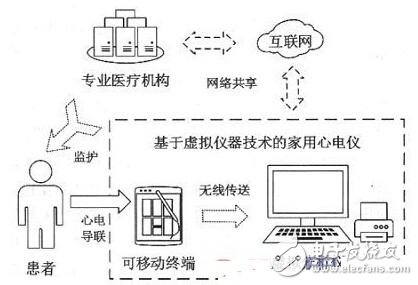
This paper designs a home ECG monitoring system based on virtual instrument technology (Figure 1), focusing on the design and implementation of mobile terminals and virtual analyzers. The mobile terminal is developed based on 51 MCU and related analog circuits, and the virtual analyzer is programmed by LabVIEW software on the computer. The patient's ECG information is collected by the mobile terminal, processed to obtain a standardized digital signal, and wirelessly transmitted to the virtual analyzer for graphical display, recording and data analysis functions. The virtual analyzer can also share information with professional medical institutions through the Internet, and achieve the purpose of focusing on specific objects.
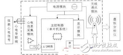
1 mobile terminalThe mobile terminal realizes the collection, transmission and local display of the ECG signal, and is composed of five parts: the ECG information acquisition module, the main controller, the display module, the power module and the wireless communication module (Fig. 2).
The surface ECG signal is extremely weak, and it is easy to be mixed with noise. The ECG information acquisition module extracts the effective information through repeated amplification and filtering. The signal processing steps mainly include: preamplifier, bandpass filtering, power frequency notch, secondary amplification and level up (Figure 3).
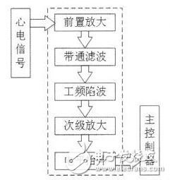
The preamplifier section uses a differential amplifier circuit with high input impedance and high common mode rejection ratio. The bandpass filtering part is composed of a high-pass filter and a low-pass filter, and the design passband is 0.3-100 Hz. 50 Hz power frequency interference is suppressed by a double T trap circuit. After filtering out the noise, it is necessary to pass the secondary amplification and level uplift to make the waveform cover the voltage range of the A/D sampling, and ensure the conversion precision, which is realized by the in-phase amplification circuit and the addition circuit. The signal is finally output to the A/D module of the main controller STC12C5A08AD.
In order to ensure the performance of the system, the preamplifier circuit uses the AD620 with high precision and high input impedance instrumentation amplifier. The other circuits are designed with high precision low noise operational amplifier OP07.
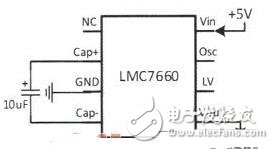
1.2 power moduleThe system is powered by a 5V lithium battery, but since the op amp requires both positive and negative power supplies, a 5V voltage conversion circuit is designed with the LMC7660. The LMC7660 is a highly integrated CMOS voltage converter that requires only a single 10μF charge capacitor (Figure 4) for a wide operating voltage range and high voltage conversion efficiency.
1.3 wireless communication moduleThe wireless communication module is the link between the mobile terminal and the virtual analyzer, ensuring the portability and flexibility of the system. APC220 integrated half-duplex micro-power wireless data transmission module is adopted. This module is embedded in high-speed single-chip microcomputer and high-performance radio frequency chip. It provides a common interface for the bottom layer setting, which is convenient for online parameter modification. It does not need to write complex setup and transmission programs, which greatly improves development. effectiveness. Its pin definition is shown in Table 1.

The mobile terminal and the virtual analyzer are each equipped with an APC220 module, and the terminal and the APC220 are directly connected through the serial port (RXD, TXD), and the analyzer communicates with the APC220 through the TTL-USB converter.
1.4 main controller and display moduleThe main controller is the core of the whole mobile terminal, receives the waveform output from the information acquisition module, realizes the A/D conversion and data output function, and selects the 51-core single-chip STC12C5A08 AD.STC12C5A08AD is a low-power, high-performance 8-bit. The microcontroller has 8k bytes of Flash and 1280 bytes of RAM, and integrates 8-channel 10-bit high-speed A/D conversion channels. The display module uses a dot matrix graphic liquid crystal display FYD12864 with a resolution of 128 & TImes; 64 points with a Chinese character library.
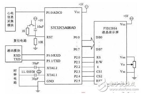
The main controller circuit includes a clock circuit, a reset circuit, an A/D interface circuit, a display interface circuit, and a serial communication circuit (FIG. 5). The MCU receives the output signal of the acquisition module through the P1.0 (ADC0) port; through the address line (P2.3, P2.4), data line (P0 port), control line (P2.0, P2.1, P2.2) , P2.5) control 12864 display; connected to the communication module through the serial port (P3.0, P3.1). The reset circuit includes a power-on reset and a button reset; the crystal oscillator's clock frequency is selected to be 11.0592MHz, ensuring accurate communication baud rate.
Fiber Optic Box,Fiber Optics Box,Fiber Optic Boxes,Fiber Optic Junction Box
Cixi Dani Plastic Products Co.,Ltd , https://www.danifiberoptic.com