Wheeled remote control robots have been used in some dangerous indoor areas such as earthquakes and fires for rescue and detection, or to carry out counter-terrorism missions. Because there are many unknown factors in these special environments, and there is no GPS signal in the room, people have to rely on advanced science and technology to obtain the navigation information of the remote control robot car. However, the current navigational sensing methods used by wheeled sports cars include visual, photoelectric, ultrasonic, odometer, etc., which are relatively easy to be disturbed by the external environment and cannot meet the needs of the vast market.
However, the inertial navigation equipment is placed in the carrier, does not rely on external information when working, does not radiate energy to the outside, and is not easily harassed. It is a self-supporting navigation system, which is superior to the above-mentioned navigation sensing example. In recent years, inertial sensors of MEMS (Micro Electro Mechanical Systems) structures have been rapidly developed along with advances in semiconductor technology, and their low-cost and high-precision expectations have been realized. The inertial navigation device composed of MEMS inertial sensors combined with the wheeled odometer can generate navigation and positioning information, reduce dependence on the external environment, and realize navigation under unknown external environmental conditions (such as lighting and wall materials).
Because the survey is carried out in the indoor area, the running characteristics of the car are different from those of the general aircraft, ship and car. Its motion trajectory changes rapidly and there is certain vibration during the movement. Therefore, the commonly used Kalman filter algorithm needs further improvement. Can be applied. The inertial sensor collects a large amount of data, and requires a large number of floating-point operations for inertial navigation. Therefore, this project uses a DSP 28335 chip with powerful digital signal processing function and a PC control terminal to realize data acquisition and sequential logic control of the inertial sensor. Communication with the drive system and map display function, with small size, low cost, low power consumption and so on.
In summary, this paper will use low-cost MEMS devices, combined with DSP and Kalman filtering algorithm, to achieve higher precision wheeled car navigation and positioning.
1 system architecture
The goal of this paper is to develop a wheeled car inertial navigation system, which can realize the PC terminal and the handheld terminal to control the wheeled car action and the data collected by the car through wifi.
Set up the system shown in Figure 1 below. TI's floating-point DSP TMS320F28335 chip is used as the main digital signal processor to collect and process the signals of each MEMS inertial sensor. The processing result is transmitted to the PC terminal through WIFI; the PC terminal is responsible for display positioning. The results and maps are displayed and a control command is sent to the cart drive system while receiving odometer information fed back by the drive system.
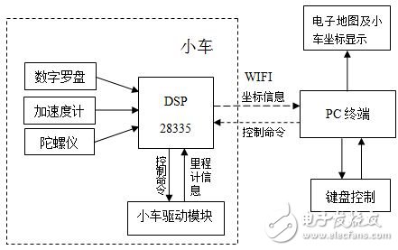
Figure 1 Overall architecture
2. Hardware plan and detailed implementation
Hardware design, mainly divided into core board and driver board. The core board includes DSP minimum system, JTAG download port design, system power supply circuit and MEMS sensor, WIFI module and so on. The main design of the driver board is the drive module of the DC motor.
2.1 core board design
2.1.1 Power circuit design
The TMS320F28335 requires different voltages during operation: the core voltage (1.9 V) and the I/O supply voltage (3.3 V), which are sensitive to the power supply, so the power supply is implemented using two output power devices TPS767D318, as shown in Figure 2. Shown. At the same time, according to the simulation experiment and the actual welding circuit test, it is better to use some protective capacitors with a capacitance value of not less than 10uf, and the chip capacitor cannot be used, otherwise the operation is unstable.
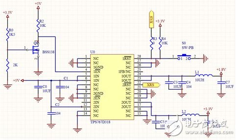
Figure 2 DSP power supply design
In the power supply design, considering that the TPS767D318 chip can generate a reset signal, there is no additional reset circuit for the DSP on the core board.
2.1.2 JTAG download port circuit design
Figure 3 shows the JTAG circuit. Select the 14-pin emulation interface according to the emulator's communication pin. Also note that the EMU0 and EMU1 signals must be connected to the power supply through pull-up resistors, where the pull-up resistor is 10kΩ.
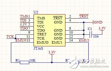
Figure 3 JTAG circuit design
2.2 car drive board design
In this device, we use the BTS7960 as the DC motor driver chip. The BTS7960 is an integrated high-current half-bridge driver that contains an NMOS, a PMOS, and a half-bridge gate drive. It has an internal impedance of 17mΩ at IOUT = 9 A, VS = 13.5V, and Tj = 25 °C. . The device uses two DC large motors, as shown in Figure 4, which is a circuit diagram that drives the front and rear steering of a single motor.
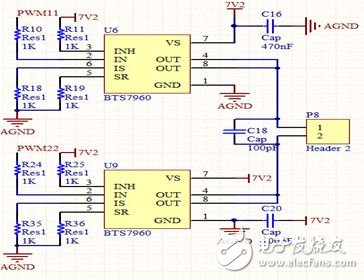
Figure 4 drive module circuit design
In the motor drive here, you need to pay attention to a detail, that is, the motor may generate a reverse electromotive force during the rotation process, so that the current is too large, causing the microcontroller to reset or even burn the chip. Therefore, in the design process, you can consider adding optocoupler isolation or diode at the PWM input to the motor drive interface. As shown in Figure 5, the driver board selects the optocoupler design isolation circuit of tlp521-4 to reduce the voltage interference, reduce the design of the circuit, and also pull the I/O level of the four PWMs from 3.3. To 5V.
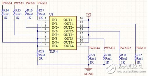
Figure 5 TLP521 isolation circuit
3. Software design and implementation
In software program design, the main application of nine-degree-of-freedom inertial navigation sensor (ITG3200+ADXL345+HMC5883L), combined with DSP and Kalman filter algorithm, can achieve higher precision wheeled car navigation and positioning.
3.1 sensor device programming
Nine-degree-of-freedom inertial navigation sensors have been used in many fields, such as drones and disaster relief robots. It includes the ITG3200 three-axis gyroscope, the HMC5883L three-axis magnetic induction sensor and the ADXL345 three-axis accelerometer, so you can get real-time values ​​of acceleration, angular velocity and angle.
The ITG3200 is a MEMS three-axis gyroscope that measures the rotational angular velocity of the car and also converts the angular velocity into the tilt angle of the car through integration. In the program, the initialization of the ITG3200 is as follows:
Unsigned char Init_ITG3200(void)
{
Unsigned char Return1, Return2, Return3, Return4;
Unsigned char Data;
Data = 0x00;
Return1 = IIC_WriteData(0xD0, 0x3E, &Data, 1);
Data = 0x07;
Return2 = IIC_WriteData(0xD0, 0x15, &Data, 1);
Data = 0x1E;
Return3 = IIC_WriteData(0xD0, 0x16, &Data, 1);
Data = 0x00;
Return4 = IIC_WriteData(0xD0, 0x17, &Data, 1);
If(Return1 && Return2 && Return3 && Return4)
Return 1;
Else
Return 0;
}
Its specific function implementation can read its value through SCI in the main program. The value read is the angular velocity, which is not affected by the motion of the car. Therefore, the signal noise is small, and the angle of the trolley can be integrated by it, which can smooth the signal and make it more stable.
Since the device is to perform survey search in different indoor areas, plus an unknown environment, the angular velocity signal may have a certain deviation, which may cause a large error in the angle after the integration, and the actual value cannot be obtained. In order to eliminate this cumulative error due to the deviation, the ADXL345 triaxial acceleration sensor is added to the device to correct the obtained angle information. The ADXL345 is initialized as follows:
Unsigned char Init_ADXL345(void)
{
Unsigned char Return1, Return2, Return3, Return4;
Unsigned char Data;
Data = 0x0b;
byReturn1 = IIC_WriteData(0xA6, 0x31, &Data, 1);
Data = 0x08;
Return2 = IIC_WriteData(0xA6, 0x2c, &Data, 1);
Data = 0x08;
Return3 = IIC_WriteData(0xA6, 0x2d, &Data, 1);
Data = 0x80;
Return4 = IIC_WriteData(0xA6, 0x2e, &Data, 1);
Data = 0x00;
Return4 = IIC_WriteData(0xA6, 0x1e, &Data, 1);
Data = 0x00;
Return4 = IIC_WriteData(0xA6, 0x1f, &Data, 1);
Data = 0x05;
Return4 = IIC_WriteData(0xA6, 0x20, &Data, 1);
If(Return1&&Return2&&Return3&&Return4)
Return 1;
Else
Return 0;
}
The angle obtained by the ADXL345 is compared with the angle after the gyroscope is integrated, and then the deviation of the gyroscope is used to change the output of the gyroscope so that the integrated angle is slowly corrected to the actual angle, as shown in FIG.
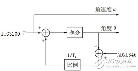
Figure 5 Correcting the angle with the acceleration sensor
The HMC5883L three-axis magnetic induction sensor acts as a compass, and in horizontal situations, the heading can be calculated without the need for other sensors. Its initialization is as follows:
Unsigned char Init_HMC5883(void)
{
Unsigned char Return1;
Unsigned char Data;
// When Bit4 Bit3 is equal to 11, select the range of 2000 degrees/second.
Data = 0x00;
Return1 = IIC_WriteData(0x3C, 0x02, &Data, 1);
If(Return1)
Return 1;
Else
Return 0;
}
Since the device is to be operated in different environments, it does not maintain the level of time, and an acceleration sensor is required to correct the error due to the tilt.
3.2 Kalman filter algorithm application
Therefore, the device performs survey search in the indoor area. The running characteristics of the car are different from those of ordinary airplanes, ships and cars. Its movement changes rapidly, the trajectory is uncertain, and it is suitable for working in different environments. Therefore, the commonly used Kalman filtering algorithm needs Further improvements can be applied. Kalman filtering uses the previous estimate and the most recent observation to estimate the current value of the signal. It is estimated using the state equation and the recursive method, and its solution is given as an estimate. The Kalman filter used in accelerometers and gyroscopes is as follows:
// float gyro_m: the amount measured by the gyroscope (angular velocity)
//float incAngle: the angle value measured by the accelerometer
#define dt 0.0015//Kalman filter sampling frequency
#define R_angle 0.71 //Measure the covariance of the noise (ie the measurement deviation)
#define Q_angle 0.0001// covariance of process noise
#define Q_gyro 0.0003 //Covariance of process noise Process noise covariance is a row and two column matrix
Float kalmanUpdate(const float gyro_m,const float incAngle
{
Float K0;//Another function with Kalman gain for calculating the optimal estimate
Float K1;//a function containing Kalman gain, used to calculate the deviation of the optimal estimate
Float Y0;
Float Y1;
Float rate; / / remove the angular velocity after the deviation
Float Pdot[4];//The differential matrix of the process covariance matrix
Float angle_err;//angle offset
Float E; / / calculated process volume
staTIc float angle = 0; //lowest optimal angle of view
staTIc float q_bias = 0; // gyroscope deviation
staTIc float n[2][2] = {{ 1, 0 }, { 0, 1 }};//Process covariance matrix
Rate = gyro_m - q_bias;
/ / Calculate the differential matrix of the process covariance matrix
Pdot[0] = Q_angle - P[0][1] - P[1][0];
Pdot[1] = - n[1][1];
Pdot[2] = - n[1][1];
Pdot[3] = Q_gyro;
Angle += Rate * dt; //Angle velocity integral to get the angle
n[0][0] += Pdot[0] * dt; //calculate covariance matrix
n[0][1] += Pdot[1] * dt;
n[1][0] += Pdot[2] * dt;
n[1][1] += Pdot[3] * dt;
Angle_err = incAngle - angle; //calculate the angular deviation
E = R_angle + P[0][0];
K0 = n[0][0] / E; //calculate the Kalman gain
K1 = n[1][0] / E;
Y0 = n[0][0];
Y1 = n[0][1];
n[0][0] -= K0 * Y0; //With the new covariance matrix
n[0][1] -= K0 * Y1;
n[1][0] -= K1 * Y0;
n[1][1] -= K1 * Y1;
Angle += K0 * angle_err; // give the best estimate
Q_bias += K1 * angle_err;// deviation from the new optimal estimate
Return angle;
}
The data smoothing at the time of filtering filters out the fluctuation noise generated near the acceleration output voltage.
4 Experimental test and result analysis
After the device hardware and software are built, the original PC-side software and tablet Android software are searched for Wi-Fi and automatically connected to the LAN. In a laboratory test environment, the car can travel freely and feed back real-time data and test comparisons.
4.1 Heading angle data test
The heading angle collected by the HMC5883L has random fluctuations, so it is possible to perform average filtering for multiple acquisitions to improve the data stability of the system output. Figure 6 shows the data of the heading angle before and after filtering in a certain period of time.
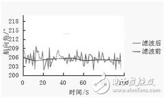
Figure 6 Navigation angle data acquisition and comparison chart
The comparison of the data in the above figure shows that the error of the data collected by the heading is greatly reduced after the average sampling and filtering optimization, which is much more stable than the original data, indicating that the filtering effect is obvious.
4.2 Angle data test
The data obtained at the angle can be converted to roll and pitch angles using data from the ADXL345 and ITG3200. The Kalman filter is combined to filter the data to achieve more accurate experimental results. Table 1 below shows the data and error of the angle before filtering 1, and Table 2 shows the data and error of the angle after filtering.
Table 1 Data and error of the angle before filtering

Table 2 Data and error of filtered angle

It can be seen from the test data of Table 1 and Table 2 that after filtering, the maximum error is reduced from 3.8 to -0.4, and is generally within 1 °, which greatly improves the output precision of the angle.
5 Conclusion
The wheeled trolley indoor inertial navigation device designed in this paper analyzes the specific implementation methods of each module of the software design. The experimental results show that the design can monitor the position information of the mobile robot in real time and can effectively control it. At the same time, its low-cost, high-precision and easy-to-operate features will be further applied to professional fields such as patrol robots and rescue robots. It will attract many investors from home and abroad to invest in it and carry out further research and development and application. A vast majority of innovation and entrepreneurial prospects, application prospects and market prospects.
Poly Solar Panel Price,Half Cut Poly Solar Panel,Polycrystalline Pv Module,Solar Polycrystalline Panel
Wuxi Sunket New Energy Technology Co.,Ltd , https://www.sunketsolar.com