This paper introduces and compares the advantages and disadvantages of voltage-type PWM controller and current-mode PWM controller, and focuses on the application of current-mode control chip UC3846 in high-power full-bridge switching power supply, and analyzes the circuit.
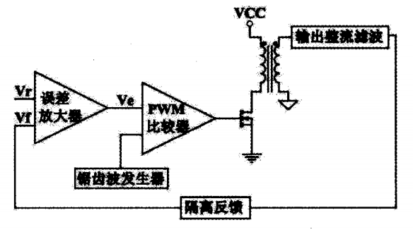
2, voltage type and current type PWM controller 2.1, voltage type PWM controllerCurrently widely used PWM controllers are controlled by voltage mode. It only samples the output voltage. The sampled signal Vf is used as a feedback signal and the reference voltage vr is amplified in the error amplifier to obtain the error signals Ve, ve and sawtooth. After the signal comparison, the PWM comparator outputs a series of high-frequency pulses to control the on and off of the switch. Its main disadvantages are: slow response, poor stability, and even oscillation when large signals change, causing power tube damage. Waiting for a fault.

Figure 1 Schematic diagram of voltage control type
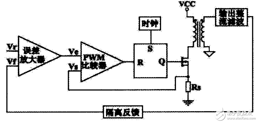
2.2, current type PWM controllerIn view of the shortcomings of the above voltage type controllers, current type control technology has been developed in the past decade. Figure 2 shows the schematic diagram of the current control type. Its working principle is to drive the power tube to conduct by using the constant frequency clock pulse to set the latch output pulse. The current pulse in the power supply circuit is gradually increased. When the amplitude on the sampling resistor Rs reaches Ue, the pulse width comparator state is inverted, the latch is reset, the drive is removed, and the power transistor is turned off. In this way, the current pulses are detected and adjusted one by one, and the purpose of controlling the power output can be achieved. The current control type is a control link that increases the current feedback inside the voltage feedback PWM control loop. Due to the presence of the voltage loop and the current loop double loop system, the line voltage regulation rate, load regulation rate and transient response characteristics of the converter are greatly improved. . However, it should be noted that the peak current control type circuit needs to add a slope compensation circuit when the circuit duty ratio is greater than 50%.

Figure 2 Schematic diagram of current control type
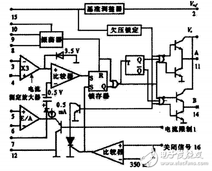
3. Introduction of pulse width modulation chip U03846UC3846 was originally introduced by the company's current pulse width modulation chip. The chip uses a high current totem pole type double-ended output, output peak current up to 500mA, can directly drive the FET, built-in precision bandgap adjustable reference voltage, high Frequency oscillator, error amplifier, differential current sense amplifier, undervoltage lockout circuit and soft start circuit with automatic shutdown function. Its main advantages are full-featured, automatic feedforward compensation, undervoltage protection, terminal lock protection, and better load response characteristics. The peripheral control circuit is simple and the operating frequency is up to 500KHZ. The maximum input voltage is 40V, and the reference voltage output is typically 5.1V. The internal block diagram is shown in Figure 3.

Figure 3 UC3846 internal block diagram
Smd Led,Smd Fnd Display,Smd Led 0603 Display,Smd Led 0805 Display
Wuxi Ark Technology Electronic Co.,Ltd. , https://www.arkledcn.com