First, the research background
Testing a base station antenna in a microwave darkroom is a common method. Due to the limitation of the size of the darkroom, the far-field test conditions are often not met for antennas with higher gain. In this case, the test results are quite different from the test results in the far field. This report presents a method for calculating the far-field pattern from a pattern measured at a quasi-far field distance.
Second, the basic principle of the modified algorithm
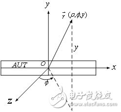
The AUT shown in FIG. 1 is a base station antenna, and the size of the antenna along the y-axis direction is small, and it is easy to satisfy the far-field condition, and the size in the x-direction is large, which does not satisfy the far-field condition. This method can be used to correct the pattern of such an antenna.

Figure 1 Antenna coordinate system
Use oy as the axis to make a minimum cylinder that can completely surround the antenna to be tested. Set the radius of the cylinder to rmin. Outside the cylinder, the electric field generated by the antenna can be expressed as a vector wave function. ![]() Weighted sum, ie
Weighted sum, ie
![]() (1)
(1)
Let the field point be in the xoz plane (ie y=0), and when Ï is large, equation (1) can be expressed as
![]() (2)
(2)
Of which: Nm=krmin+10
Since the field point (Ï, φ, 0) is already in the quasi-far area of ​​the antenna, and Ï is already large relative to the vertical dimension of the antenna (y-axis direction), the integral in the above equation can be performed by the one-dimensional phase-preserving method. Calculate and take into account ![]() And thus have
And thus have
 (3)
(3)
For any linearly polarized electric field component can be expressed as
 (4)
(4)
If the electric field measured at Ï = Ïo is Em, then there is
 (5)
(5)
Can be found
 (6)
(6)
Substituting Cn into equation (5), let Ï→∞, then get the far field of the antenna as
![]() (7)
(7)
Where C is a constant independent of the angle and can be omitted. The far field pattern of the antenna is
![]() (8)
(8)
Based on the above relationship, it is easy to obtain the difference between the gain of the antenna under far field conditions and the gain under the quasi-far field condition.

220Uh Inductor,High Current Inductor,Power Inductor,Toroidal Core Inductor
IHUA INDUSTRIES CO.,LTD. , https://www.ihua-transformer.com