Electric blankets without temperature control are not only difficult to obtain a comfortable bed temperature, but also have high energy consumption and fire hazards. Electric blankets with bimetal thermostats have improved in terms of energy efficiency and safety, but it is difficult to adjust the temperature. The above disadvantages can be overcome by using a PTC thermistor temperature control circuit.
1 principle circuit
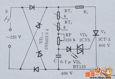
The electric blanket temperature control circuit is composed of a rectifier circuit and a temperature control circuit. The basic principle is shown in Figure 2.11.1. In the figure, RT1 and RT2 are PTC thermistors, which are used to detect the temperature in different areas, and with RP, C, VD6 constitutes a trigger circuit for the unidirectional thyristor VS. The RP has a preset thermostat value.
When the power is turned on, the mains is directly rectified by the bridge circuit, and then charged to C through RT1, RT2, and RP. When the charging voltage of C reaches a certain value, the V1 is discharged through VD5 and VD6, and the VS is triggered to conduct, and the heating wire RL is electrically heated to enter a temperature rising state. As the temperature of the electric blanket increases, the resistance of RT1 and RT2 increases, the time constant of the charging circuit will gradually increase, the conduction angle of VS will become smaller and smaller, and the heating power of RL will decrease. When the temperature of the electric blanket rises further to a predetermined value, the resistance of RT1 and RT2 will increase stepwise, up to 500KΩ, the conduction angle of VS is approximately zero, and the circuit load current is so small that RL hardly heats up. Then, the electric blanket enters a constant temperature and keeps warm. Conversely, when the temperature of the electric blanket drops below the preset value by about 5 °C, the VS will re-trigger the conduction, and the RL will be electrically heated again. This operation is repeated to achieve the purpose of automatic constant temperature.

Figure: Electric blanket temperature control circuit
2 main components selection
The PTC thermistor should have a Curie temperature of 30 ° C, a normal temperature resistance of 5 KΩ, and a withstand voltage of 500 V or more. VS is selected according to the power of RL. The model selected in this circuit can meet the requirements of general electric blankets. CSelect a polycarbonate film capacitor with good insulation properties.
3 Installation and commissioning
The recommended installation method is to embed two PTC thermistors in the dense part of the heating wire. For example, the center of the foot and waist. In addition, the circuit is directly connected to the mains, and the PTC thermistor and the lead end buried in the electric blanket should have good insulation measures.
The mechanical Buzzer uses a magnet to move a reed up and down quickly to emit a lower-pitch buzz! It's quieter than the piezoelectric buzzer but uses more power, so you the terminals will have to be closer to the battery packs. To use them, you'll need to match the wire colors to the wires from the battery pack.
Piezo Beeper,Mechanical Buzzer,Piezo Mechanical Buzzer,Low Frequency Mechanical Buzzer
Jiangsu Huawha Electronices Co.,Ltd , https://www.hnbuzzer.com