A multiplex section refers to a maintenance section (including two RSTs and a fiber optic cable between them) between the regenerator section terminals (RST) of two devices. The path between the two multiplex section path termination functions (including these two functions) in the Synchronous Digital Hierarchy (SDH) standard.
The multiplex section function mainly involves the use of sub-layers to complete the multiplex section layer protection, and thus the implementation is relatively complicated. The network protection function is a very significant and important function of the SDH network element, and it is also a function that requires a very detailed design. From the perspective of the atomic model, the multiplex section protection function splits the path termination function into sub-layer functions. The following describes the network element device with the four-fiber bidirectional multiplex section switching function, which is currently used more frequently in the trunk, according to the atomic function specification of the device. The basic functions are still mainly reflected in the terminal function and the adaptation function, and the protection function is mainly embodied in the connection function.
SDH uses time multiplexing. For example, a level that represents "0 or 1" in 1 second becomes a signal that can represent N "0 or 1" levels in 1 second; SDH is generally 1 in 1 4, so there are STM-1, STM-4, STM-16, STM-64, STM128; another concept is to multiplex low-speed signals such as 2M or 1.5M, 34M, 45M into the most basic STM-1 signal (ie 63 2M, or 4 34M, or 3 45M)
How sdh reuse worksAlthough there are many routes for multiplexing a signal into an SDH STM-N signal, it is necessary to uniquely multiplex the route for a country or region. China's optical synchronous transmission network technology system stipulates the PDH series based on 2Mbit/s signal as the payload of SDH, and selects the multiplexing route of AU-4. Its structure is shown in the figure.

China's SDH basic multiplexing mapping structure
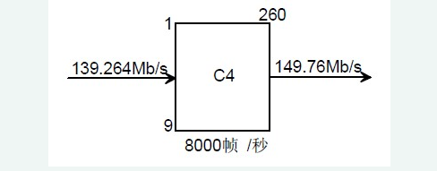
1. 140Mbit/s multiplexing into STM-N signalThe frame of the C4 signal has 260 columns &TImes; 9 rows (when the PDH signal is multiplexed into the STM-N, its block frame remains at 9 lines), then the signal rate after the E4 signal is adapted (ie, the C4 signal) The rate) is: 8000 frames/second & TImes; 9 lines & TImes; 260 columns & TImes; 8bit = 149.760 Mbit/s.
C4 frame structure diagram
The base frame of C4 (9 rows × 260 columns) can be divided into 9 subframes, one for each subframe. Each sub-frame can be divided into 20 units (20 13-byte blocks) in 13 bytes. The first byte of the 20 13-byte blocks of each sub-frame is: W, X, Y, Y, Y, X, Y, Y, Y, X, Y, Y, Y, X, Y, Y , Y, X, Y, Z, a total of 20 bytes, the second to the 13th byte of each 13-byte block is placed 140Mbit / s information bits. See picture:
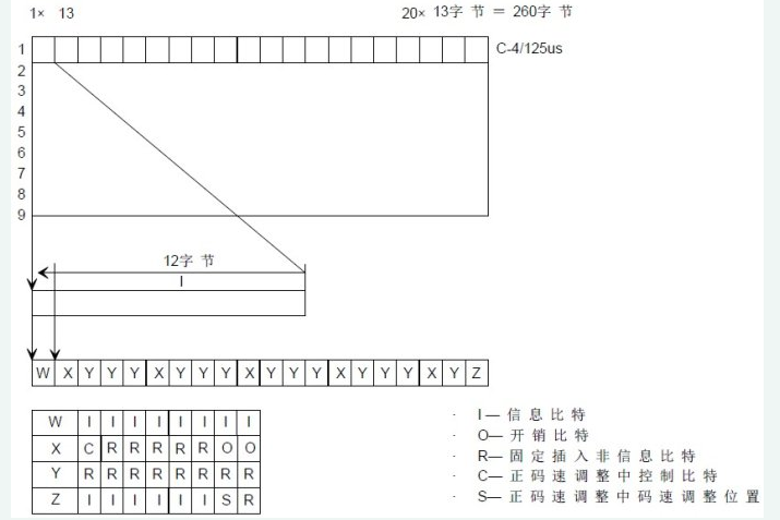
Subframe structure of C-4
The rate adaptation of the E4 signal is achieved by the first byte of a total of 180 13-byte blocks of 9 subframes. C4 subframe = 241W + 13Y + 5X + 1Z = 260 bytes = (1934I + S) + 5C + 130R + 10O = 2080bit.
Information bits I: 1934; fixed stuffing bits R: 130; overhead bits O: 10; adjustment control bits C: 5; adjustment opportunity bits S: 1.
In order to be able to monitor the channel signal of 140 Mbit/s, a column overhead byte (high-order channel overhead VC4-POH) is added in front of the block frame of C4 in the multiplexing process, and the signal becomes the VC4 information structure. See the picture below.
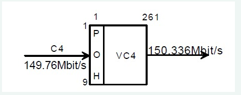
VC4 structure diagram
VC4 is actually the information payload of STM-1 frames. The PDH signal is packaged into C, and the corresponding channel overhead is used to form the information structure of VC. This process is called mapping.
The goods were packed in standard packages and can now be loaded onto the STM-N. The location of the load is its information payload area. This problem arises when loading goods (VC). When the speed at which the goods are loaded is inconsistent with the time the truck is waiting to be loaded (the STM-N frame period is 125 μs), the position of the goods in the trunk is “floatingâ€. So how can we correctly separate the package at the end? SDH uses a management unit pointer (AU-PTR) in front of VC4 to solve this problem. At this point, the signal changes from VC4 to the information structure of the management unit AU-4, as shown in the figure.
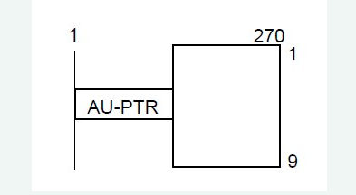
AU-4 structure diagram
Although the package may "float" within the car (information payload area), the position of the AU-PTR itself within the STM frame is fixed, why? The AU-PTR is not in the payload area, but is along with the segment overhead. This ensures that the receiving end can correctly find the AU-PTR in the corresponding position, and then locate the VC4 through the AU pointer, thereby separating the VC4 from the STM-N signal.
One or more AUG----------------------------------------------
With only the last step left, AU-4 is added to the corresponding SOH to synthesize the STM-1 signal, and the N STM-1 signals are interleaved into STM-N signals by byte interleaving.
Second, 34Mbit/s is multiplexed into STM-N signalThe same 34Mbit/s signal is first adapted to the corresponding standard container-C3 by code rate adjustment, and then the corresponding channel overhead C3 is packed into VC3. The frame structure at this time is 9 rows×85 columns. In order to facilitate the location of the VC3, so that it can be directly detached from the high-speed signal, a 3-byte pointer is added to the frame of the VC3--TU-PTR (branch unit pointer), and the information structure at this time It is the tributary unit TU-3 (information structure corresponding to the signal of 34 Mbit/s).
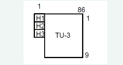
TU3 structure diagram after loading TU-PTR
The frame structure of TU3 is a bit broken. First, fill the gap part to form the frame structure shown in the figure.
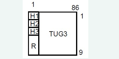
TU3 frame structure diagram after filling the gap
In the figure, R is the pseudo-random information inserted, and the information structure at this time is TUG3 - the branch unit group.
The three TUG3s are combined into a C4 signal structure by byte interleaving multiplexing, and the composite process is shown in the figure.
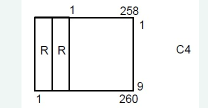
C4 frame structure diagram
The rest of the work at this time is to go to C4→STM-N: C4→VC4→AU-4→AUG→STM-N.
3. 2Mbit/s multiplexing into STM-N signalFirst, the 2Mbit/s PDH signal is loaded into the corresponding standard container C12 through rate adaptation. In order to facilitate the rate adaptation, the concept of multiframe is adopted, that is, four C12 base frames are combined into one multiframe. The base frame rate of C12 is also 8000 frames/second, then the frame rate of C12 multiframe is 2000 frames/second.
The C12 base frame structure is a 9×4-2 byte notched block frame, and 4 base frames form a multiframe. The C12 multiframe structure and byte arrangement are as shown.
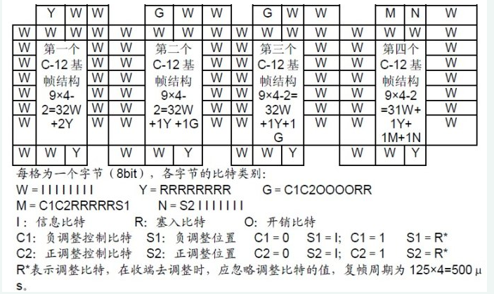
C-12 multiframe structure and byte arrangement
In order to monitor the performance of any 2Mbit/s channel signal in real time in the transmission of SDH network, C12 needs to be repackaged - adding the corresponding channel overhead (lower-order channel overhead), making it the information structure of VC12. Here LP-POH (low-order path overhead) is added to the gap in the upper left corner of each base frame, and a multiframe has a set of low-order path overheads, a total of 4 bytes: V5, J2, N2, K4. A C12 multiframe is loaded with 4 frames of PCM30/32 signals, so a group of LP-POH monitors the transmission status of the 4 frames of PCM30/32 signals.
In order to enable the receiver to correctly locate the VC12 frame, add 4 bytes of TU-PTR to the 4 gaps of the VC12 multiframe. At this time, the information structure of the signal becomes TU12, 9 rows × 4 columns. The TU-PTR indicates the specific location of the starting point of the first VC12 in the multiframe in the TU12 multiframe.
The three TU12s synthesize TUG-2 through byte interleave multiplexing, and the frame structure at this time is 9 rows x 12 columns.
Seven TUG-2s synthesize the information structure of TUG3 through byte interleave multiplexing. Please note that the information structure of the 7 TUG-2 synthesis is 9 rows × 84 columns. To satisfy the information structure of TUG3, 9 rows × 86 columns, two columns of fixed stuffing bits must be added before the information structure of the 7 TUG-2 synthesis. . as the picture shows.
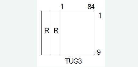
TUG3 information structure
From the multiplexing step of 2Mbit/s multiplexing into STM-N signals, it can be seen that 3 TU12s are multiplexed into one TUG2, 7 TUG2s are multiplexed into one TUG3, 3 TUG3s are multiplexed into one VC4, and one VC4 is multiplexed into One STM-1, that is, the 2Mbit/s multiplexing structure is a 3-7-3 structure. Since the multiplexing method is byte interleaving, the arrangement of 63 VC12s in one VC4 is not arranged in order. The sequence number of the first TU12 differs from the sequence number of the TU12 immediately after it by 21.
There is a formula for calculating the sequence number of TU12 at different locations in the same VC4:
VC12 serial number = TUG3 number + TUG2 number -1) 3 + (TU12 number - 1) × 21.
The location of the TU12 in the VC4 frame refers to two TU12s with the same TUG3 number, the same TUG2 number, and the TU12 number difference of 1. Note: The number here refers to the position number in the VC4 frame, the TUG3 number range: 1~3; the TUG2 number range: 1~7; the TU12 number range: 1~3. TU12 serial number means this TU12 is
VC4 frame 63 TU12 The first few TU12s in the order of multiplexing. See picture.
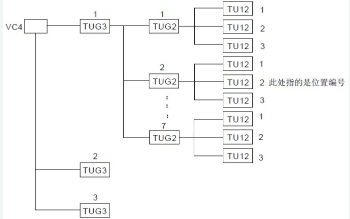
Emission structure of TUG3, TUG2 and TU12 in VC4
Shenzhen Kaixuanye Technology Co., Ltd. , https://www.icoilne.com