as the picture shows.
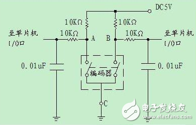
Figure: Reference application circuit diagram
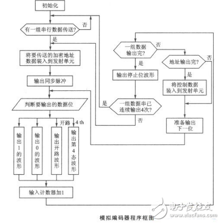
Application Circuit of Encoder (2) Software Design and Application of Encoder VD5026 with Single Chip MicrocomputerEach set of serial data output waveforms of the VD5026-4 consists of a sync pulse, a 12-bit encrypted address (and control data), and a 1-bit stop bit. The code pulse output order is AO~A7, A8/DO~All/D3, and each group of serial data is output at least 4 times. After mastering the serial data output format and its data verification mode, pulse period, pulse duty ratio and its corresponding data relationship, the application program is written according to the requirements of the encoding pulse output, so that the microcontroller realizes the function of the encoder. The block diagram of the analog encoder is shown below.
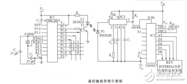
The infrared remote control keyboard designed with this technology has been applied to the "color remote monitoring system". The principle of the remote keyboard is shown below.
This circuit adopts single-chip AT89C2051, which is a cost-effective single-chip microcomputer. The device adopts 80C31 core, and the command system and pins are fully compatible with MCS-51TM. There is 2KB of reprogrammable flash memory, the number of programming can be erased/written 1000 times, and the data is saved for 10 years.
The decoder VD5027 has 4 bits of data output and can be translated into 16 states to meet 3×4 keyboard requirements.
When the MCU queries a key press, it generates a code pulse corresponding to the key value. The coded pulse signal is modulated with a 38 kHz pulse signal and transmitted through a transmitting tube (SE303A). The infrared receiving diode (PH302B) converts the received infrared signal into an electrical signal, which is amplified by the infrared remote control receiver CX20106 and becomes a pulsed electrical signal. After the signal is shaped and amplified, it is restored to the encoded pulse output corresponding to the key value, and sent to the 14-pin DIN input terminal of the decoder VD5027.
When the VD5027 receives the first series of encoded pulse signals, if it is exactly the same as the address set by VD5027, the transmitted DO-D3 four-bit data code is sent to the register (and changed from serial code to parallel code). When the second series of identical coded pulse signals arrive, it is checked again. If the address is correct and the control data matches the first time, the logic control circuit in VD5027 sends a control signal, and the control data of the register is input into the latch and output to the DO to D3 terminals of VD5027. At the same time, the TV terminal changes from low level to high level, indicating that decoding is effective.
After receiving the valid decoding signal, the host reads the output data DO~D3 from the VD5027, decodes the code of the key value, and performs the corresponding operation.
Divided into product components by encoder structure and encoder components;
According to the way of use, it is divided into: rotary and linear;
According to the technical principle, it is divided into: contact type (brush mechanical contact) and non-contact type (including: optical type, photoelectric induction type, magnetic induction type, magnetic induction type...);
According to the working principle, it is divided into: incremental type and absolute type.
2, part of the encoder component products (Figure 1)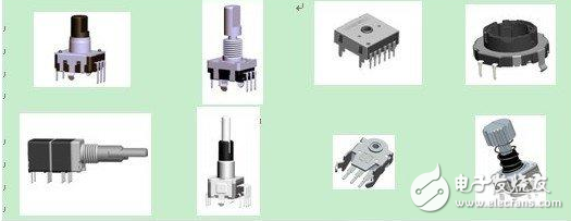
(Figure 1: Encoder component)
3, the working principle of the encoder componentsThis article will introduce the working principle and application of incremental encoder and absolute encoder.
In the body of the encoder (pulse code disc), the metal conduction area and the plastic insulation area are prepared in advance according to different product requirements, and the angle and shape of the conduction area and the insulation area determine the final signal output form of the product.
3.1, incremental encoderDuring the rotation process, two or more sets of encoders with periodic changes and phase timing differences can be output.
(1) Product features:
a) can be rotated 360 degrees;
b) during the rotation process, it can generate output signals with high and low periodic changes, without fixed starting point and end point;
c) can stop or start at any position;
d) When using, generally do not pay attention to the results of stopping the position, only emphasize the signal changes of the process.
(2) Product structure:
The product is mainly composed of a shaft core, a body, a bracket, a positioning piece, a contact brush and the like.
(3) Output signal:
The rotating brush core drives the contact brush to generate on/off, and outputs two or more sets of pulse signals with periodic changes and phase timing differences.
a) When outputting two sets of signals, it is generally divided into: A phase and B phase, and the phase difference between the phases is 1/4 pulse period delayed by each other, and the rotation direction of the product (signal increment or decrement) is judged according to the order of continuity. As shown in Figure 2:
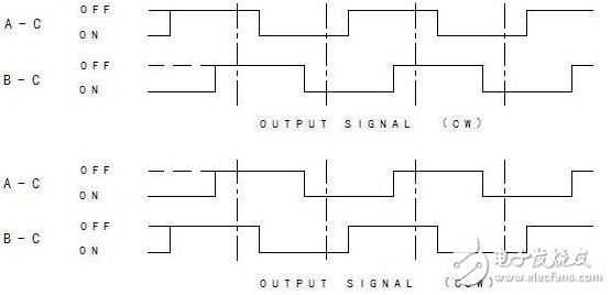
Figure 2: Two sets of signal square waves
b) When outputting three sets of signals, it is generally divided into: A phase and B phase C phase, and the signal is incremented or decremented by the sequence of the three groups of signals (time difference), and the three groups of signals are in the conduction state. Disjoint, so that the phase difference of the finished product is relatively large. Signal increase and decrease is easier to identify, more stable, and less prone to garbled, as shown in Figure 3:
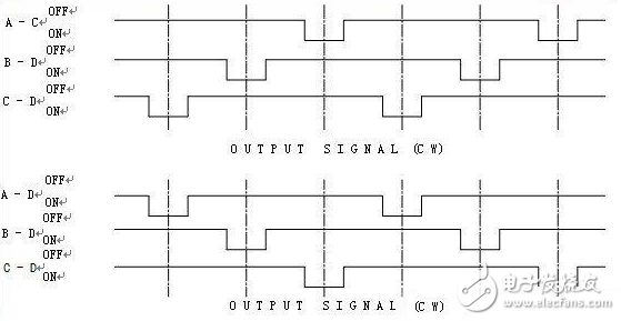
Figure 3: Three sets of signal square waves
(4) How to judge the direction of rotation and counting
According to the characteristics of the output of the pulse signal, there are two commonly used judgment methods (see Figure 4 for details):
a) Comparison method
In one pulse period, the A and B phases can be represented by four kinds of motion timings: 11, 01, 00, 10 in forward rotation and 11, 10, 00, and 01 in reverse rotation, and save this output value. Compared with the output values ​​of the next A and B phases, the direction of motion can be obtained (clockwise if output 01 is output after A and B phase outputs 11 and counterclockwise if output 10 is output 10).
This method has higher requirements on the product and is less prone to error, but it needs to start from the 11 state each time.
b) Edge trigger
The moment from the high level to the low level is called the falling edge, and the moment from the low level to the high level is called the rising edge. If the A phase output is a falling edge, the B phase appears a high level, which is a clockwise rotation; when the A phase output is a falling edge, the B phase appears a low level, which is a counterclockwise rotation. Length: 15cm font body: switching small five
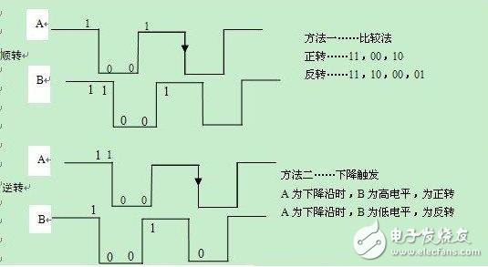
(Figure 4: comparison method, edge trigger)
3.2, absolute encoderAn encoder that outputs a binary code corresponding to the position at each positioning.
(1) Product features:
a) Set the fixed signal output mode of each gear position on the product, which is 0, 1 combination respectively. Apply this code output signal to design various functions.
b) When the forward and reverse rotations are the same gear, the output signals are consistent;
c) When using, generally do not consider the intermediate motion process, only pay attention to the output signal of the stop position.
(2) Product structure:
It is mainly composed of a shaft core, a body, a bracket, a positioning piece, a contact brush and the like. The biggest difference between it and the incremental rotary encoder is the shape of the body contact piece.
(3) Output signal:
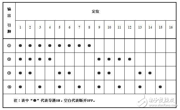
Through the rotary motion of the encoder, a fixed-coded signal with a regular correspondence is generated at the stop position, as shown in Table 1:
Table 1: Absolute coded signals
Encoder components are used in: power amplifiers, audio, mixers, car stereos, walkie-talkies, radios, mice, keyboards, oscilloscopes, microwave ovens, induction cookers, washing machines, air conditioners, etc.
Lcd Bar Display,Shelf Edge Display,Stretched Bar Lcd,Stretched Bar Display
APIO ELECTRONIC CO.,LTD , https://www.displayapio.com