Abstract: The structure of DMA (direct memory access) controller and its transmission mode of PC/AT machine system are analyzed in detail, and an example of C language programming is given.
DMA is the abbreviation of English DiretMemorAccess, namely direct memory access, DMA transfer is PC and peripherals
An important method of high-speed data exchange, a typical application is applied to the recording and playback process of the sound card. When recording, the CPU first sets the transmission parameters of the sound card and DMA. When the DMA data transmission is started (that is, the recording starts), the data transfer is performed by the DMA controller DMAC according to the PC bus. After each transfer, the DMA controller returns the bus control right and applies for the CPU interrupt, and the data is reported. After the transfer is completed, the data in the DMA data buffer is taken away by the interrupt service routine and prepared for the next data transfer (ie, recording). Since the CPU does not need to be dry during the transfer, the CPU can execute other programs during recording. The data transmission speed is greatly improved and the CPU execution efficiency is improved. It is precisely because of these advantages of DMA that the DMA data transmission method is widely used in the data acquisition process in the industrial control field. However, due to the lack of DMA programming data, DMA programming has always been a difficult point in hardware programming. This article will introduce the DMA programming method in detail using C language as an example.
1, PC / AT DMA system featuresThe PC/AT uses two 8237A-5 chips to form a cascade structure. Each 8237A-5 chip has four independent channels inside, which are represented by channel O-channel 7. However, since channel 4 is used as the cascade of the 0th slice and the 1st slice, the PC/AT system can provide a total of 7 channels of DMA data transmission, among which the channel 2 is used as the floppy disk DMA transfer service. Channel 0 is reserved for the SDIC communication adapter. The remaining channels 0, 1, 3, 5.6, and 7 are reserved for expansion. Among the 7 DMA channels, channels 0~3 are transmitted with a maximum of 64 KB of 8-bit data. Channels 5-7 are designed for maximum transmission of 64K words (128KB) in 16-bit data, all of which support the ability to address 16MB of space.
2, DMA channel address generation methodThe 8237A-5 can only manage 16-bit addresses (AI5-A0), but in order to address the 24-bit address space addressing of PC/AT machines, the 16M space of the PCAT machine is divided into multiple physical pages in the DMA system. It is guaranteed that only 16-bit address addressing is required in the DMA cycle, so a DMA page register is set for each channel in the DMA system to store the physical page number.
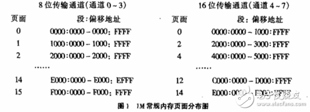
For the 8-bit transmission channel 0~3, since the address of the chip uses the byte boundary, that is, A15-A0 is a 16-bit long byte address, so each page is 64 KB, and for the 16-bit transmission channel 5-7, due to the chip address. Use the word boundary, that is, A16-AI (A0 is fixed to 0) is a 16-bit word address, so each page can reach 128KB. When calculating the address offset and the number of counts, you should especially distinguish between the two. For DOS management. 1M conventional memory, page layout shown in Figure 1:
From the DMA channel address generation method, we can see that the DMA controller can only transfer data in one physical page, so when the data is stored across pages, we must transfer the data in multiple times, guaranteeing each transmission from the surface. The time data is on the same page.

The DMA controller (DMAC) has a total of 16 port addresses and 4 page register addresses, which are divided into two categories: control DMA status and set data address.
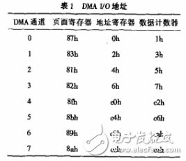
When setting up DMA transfer data, three ports are used, namely: page register, address (offset) register and data counter. Table 1 shows each channel and its corresponding 1/O port address.

When controlling the state of the DMAC, another three ports are used, namely: mode register, mask register and clear register.
Optoelectronic Information Series
Photoelectric information series laboratory related equipment
Optoelectronic Information Product,Optical Bench Experiments Physics,Optical Devices Physics,Optical Physics Properties
Yuheng Optics Co., Ltd.(Changchun) , https://www.yhencoder.com