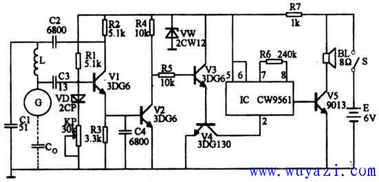
As long as the hand is close to the sensor of the burglar alarm 5~80mm, the alarm will immediately send an alarm signal. The circuit is as shown. The sensor is in. In the figure, G is used. There is a distributed capacitance Co between G and ground. Co and L, C1 and V1 form a three-point capacitor. In the loop composed of Co, C1 and L, C0 and C1 are seen from the AC path. It is connected in series. When no one is close to G, Co is small. When it is connected in series with C1, the partial pressure at both ends of Co is larger, and the partial pressure at both ends of C1 is smaller. The higher high-frequency voltage at both ends of Co is fed to V1 through C3. The base is sufficient to maintain oscillation of the three-point oscillator. At this time, the voltage drop on R3 is high, so that V2 is turned on, and the composite tube composed of V3 and V4 is turned off, and the power supply of the four-sound analog integrated circuit IC is cut off, the IC does not work, and the speaker does not sound. When someone approaches the sensor G, the Co value increases, and the high-frequency partial pressure across Co becomes small. The voltage fed to the base of V1 through C3 is insufficient to maintain V1 oscillation again, and V1 stops immediately. At this time, the voltage drop on R3 is small, V2 is cut off, V3 and V4 are turned on, the 2 pin (Vss end) of the IC is equivalent to the ground, the IC is energized, and the 3 pin outputs the siren sound signal, which is amplified by the V5. BL sounds an alarm. KP1 is used to adjust the sensing sensitivity.
V1, V2, V3 use 3DG6, etc., B is 80-150; V4 uses 3DG130, 3DG12 or 3DK4. V5 uses 9013 and so on. The integrated circuit IC uses CW 9561 four-sound IC. VD1 is a 2CP type M pole tube, and Vw is a 2CW12 Zener diode. I use a 0.31 mm enameled wire to tightly wind 20 plexiglass tubes with an outer diameter of 10 mm. The sensor G is made of a 200X150mm metal plate or a G-point lead is connected to the metal door lock.

When debugging, first check if the V3 collector voltage is around 5V. If the gap is large, check if Vw is intact; if it is normal, you can start to adjust the sensitivity. Rotate the KP1 to make the speaker sound, then adjust the KP1 back a little so that the BL just doesn't sound. At this time, the alarm should sound when the hand is approached to the copper piece G. When the hand leaves, the alarm stops and can be used. Note that the sensitivity should not be adjusted too high during use, otherwise the circuit will be unstable.
10.1 Inch Laptop,win10,win11
Jingjiang Gisen Technology Co.,Ltd , https://www.jsgisengroup.com