Chip On Board ( COB ) process
First, the silicon wafer is placed on the surface of the substrate with a thermally conductive epoxy resin coated with silver particles, and then the LED chip is placed on the surface of the substrate, heat-treated until the LED chip firmly fixes the substrate, and then the wire bonding method is used for the LED chip and the substrate. Indirectly establish a current channel. The detailed process is as follows:
The first step: crystal expansion
The LED chip film provided by the LED chip manufacturer is uniformly expanded by using an expansion machine, so that the LED chip covered on the surface of the film is closely opened, which is convenient for puncturing.
The second step: adhesive
Place the crystal-expanded crystal expansion ring on the surface of the adhesive machine without the silver paste layer, then apply the silver paste to the appropriate amount of silver paste on the PCB printed circuit board.
The third step: thorn crystal
The crystallized crystal expansion ring is placed outside the thorn crystal frame, and the operator punches the LED chip on the PCB printed circuit board with a lancet under the microscope.
Step 4: Put in a hot cycle oven
Put the punctured PCB printed circuit board into the heat cycle oven for a period of time, and take it out after the silver paste is solidified (not long-time release, otherwise the LED chip coating will be baked yellow, that is, oxidation, forming a difficulty for bonding).
The fifth step: sticky chip
Put a proper amount of red glue (or black glue) on the IC position of the PCB printed circuit board with a dispenser, and then place the IC die on the red or black glue with an anti-static vacuum pen.
Step 6: Drying
Place the bonded die in a hot-circulating oven and place it on a flat heating plate for a period of time. It can also be cured naturally (longer time).
Step 7: Bonding (also called line)
The aluminum wire bonding machine is used to bridge the wafer (LED die or IC chip) to the pad aluminum wire on the PCB board, that is, the inner lead of the COB is soldered to 99led.net.
Step 8: Pretest
Use a special inspection tool to detect the COB board and repair the unqualified board.
Step 9: Dispensing
The dispenser is equipped with a suitable amount of AB glue to the bonding LED die. The IC is packaged in black plastic and then packaged according to customer requirements.
Step 10: Curing
The sealed PCB printed circuit board is placed in a thermostatic oven for constant temperature and static setting, and different drying times can be set according to requirements.
The eleventh step: post test
The sealed PCB printed circuit board is then tested for electrical performance with professional testing tools to distinguish the good and bad grades.
The COB package is in the form of aluminum substrate COB package, aluminum substrate MCOB package, ceramic COB package, etc. Currently, dimmable LED bulbs , LED fluorescent lamps ( LED tubes ), LED spotlights, LED downlights , which are manufactured by MCOB/COB surface light source, Products such as LED ceiling lamps significantly reduce the cost of the product while improving the stability of the product. Chengdu Chaoyue uses the illumination system manufactured by MCOB/COB LED surface light source to effectively avoid the string light and zebra pattern caused by the SMD technology LED lamp. The MCOB/COB surface light source is used to manufacture the Chengdu LED bulb and LED fluorescent lamp. The LED light tube, LED spotlights, LED downlights, and LED ceiling lights make the exhibits in the store and museum more attractive and attractive, attracting attention and bringing more sales.
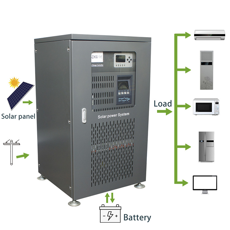
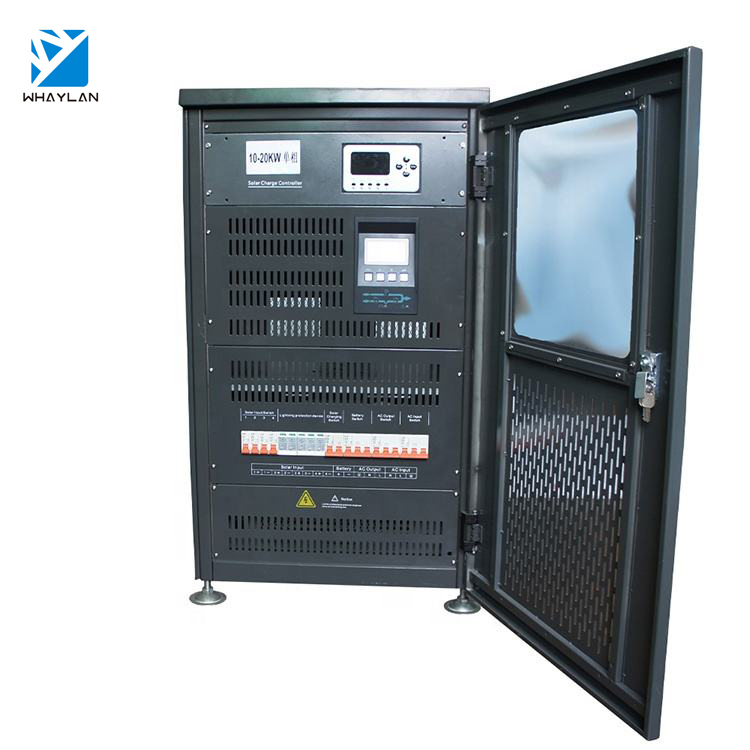
8KW-30KW MPPT Single-Phase Hybrid Inverter
8KW-30KW SIngle-Phase Hybrid Inverter(MPPT)


8KW-30KW MPPT Single-Phase Hybrid Inverter,Hybrid Solar Inverters, 48v Hybrid Solar Inverter
suzhou whaylan new energy technology co., ltd , https://www.whaylan.com