NXP Semiconductors announced on November 15 that it will introduce a fully integrated, highly flexible driver chip solution based on automotive-grade technology for automotive LED headlamps and taillight applications. The ASL1010NTK and ASL1010PHN are available in an 8/16-lead package and are the industry's first automotive LED driver ICs with many core features.
At present, automotive LEDs have been using driver chips for general-purpose solid-state lighting (SSL) applications, which are complex, expensive, and lack the core functions required for automotive applications. With the increasing popularity of automotive solid-state lighting in the automotive industry, lighting control device manufacturers and LED suppliers need more powerful and efficient solutions that enable OEMs to take full advantage of LED energy savings. Because LEDs can save about 50% in fuel consumption and power consumption in some applications compared to incandescent lamps (UMTRI, 2008).
The ASL1010NTK/ASL1010PHN driver chip integrates the core functions necessary for automotive LED lights and is a compact, all-in-one solution without the need for additional components. For the LED module design, it is beneficial to reduce costs, enhance aesthetics and improve reliability.
This system solution from NXP is extremely flexible, independent of the car platform, configuration, output voltage and number of LEDs.
This product can be used on different car platforms. NXP's LED driver chip uses an automatic buck/boost topology to safely drive up to 20 LEDs with standard automotive battery voltage; the output voltage is extremely flexible, ranging from 6V to 60V, supporting the current market Class LED.
The chip has integrated the core functions of the automotive LED driver, which helps to reduce the size of the reference design, increase design flexibility, and easily handle different configurations and LED numbers without redesigning the PCB. The integrated design eliminates the redundancy of different platforms and the need for external microcontrollers. In addition, the ASL1010NTK/ASL1010PHN driver chip is based on the ABCD9 technology node - this is NXP's automotive technology platform that drives analog mixed-signal integration.
Other key features of NXP's LED driver chip include:
1, temperature feedback function, can control the temperature and performance of the LED
2, fault detection function, can provide feedback when the LED fails
3, LED short circuit protection
4, eliminate the LED ripple current, no external components
5, external current selection and PWM programming function
6, adjustable LED internal PWM generation function, allowing the same LED light to be used as both daytime and stop lights
7, LED undervoltage and overvoltage protection
8, small package
The NXP ASL1010NTK/ASL1010PHN automotive LED driver chip will be available for sampling at the end of November and will be on display at the 2010 Munich Electronics Show in Germany.
Aluminum PCB
WHAT IS ALUMINIUM PCB
In applications where a lot of heat is generated it`s very important to dissipate this heat safely. The disadvantages of forced cooling are that it often gives rise to noise, vibrations and increased energy use. Using heat-sinks increases the costs and makes assembly more difficult, and the extra weight and volume can cause problems.
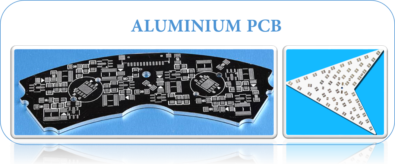
It`s often a much better solution to use specific Printed Circuit Board constructions. A solution that is frequently used is a metal core structure. Using this solution, the printed circuit board consists of an aluminium plate bearing the pattern of tracks. A thermally conductive electrical insulator is used between the tracks and the plate so that the heat can pass through to the metal core structure - such as Metal Core PCB .
The increased use of LED lighting, whereby the heat dissipated by the LED must be removed, has lead to a massive increase in the use of PCBs with aluminium cores. At the same time, the market demand for LED PCB Board is also increasing day by day.
Copper may be used as an alternative.
For High-Powered LEDs most customers use Aluminum based PCBs; for low-power LEDs standard FR4 PCBs are available as well. Our PCB fabrication specifications and build most types of metal based Printed Circuit Boards.
Aluminum Based PCBs are a unique metal-based copper clad laminate. These types of Printed Circuit Boards have good thermal conductivity, electrical insulation and very solid machining performance.
They are also known as Aluminum Clad, Aluminum base, MCPCB (Metal Clad Printed Circuit Board), IMS (Insulated Metal Substrate), Thermally Conductive PCBs etc. Aluminum PCBs were developed in the 1970s, soon after which they`re applications increased dramatically. The first application was their use in Amplification Hybrid Integrated Circuits. Now they are being used at a large scale due to which it is necessary for us to have an idea of Aluminum PCBs and their importance.
ALUMINIUM PCB STRUCTURE:
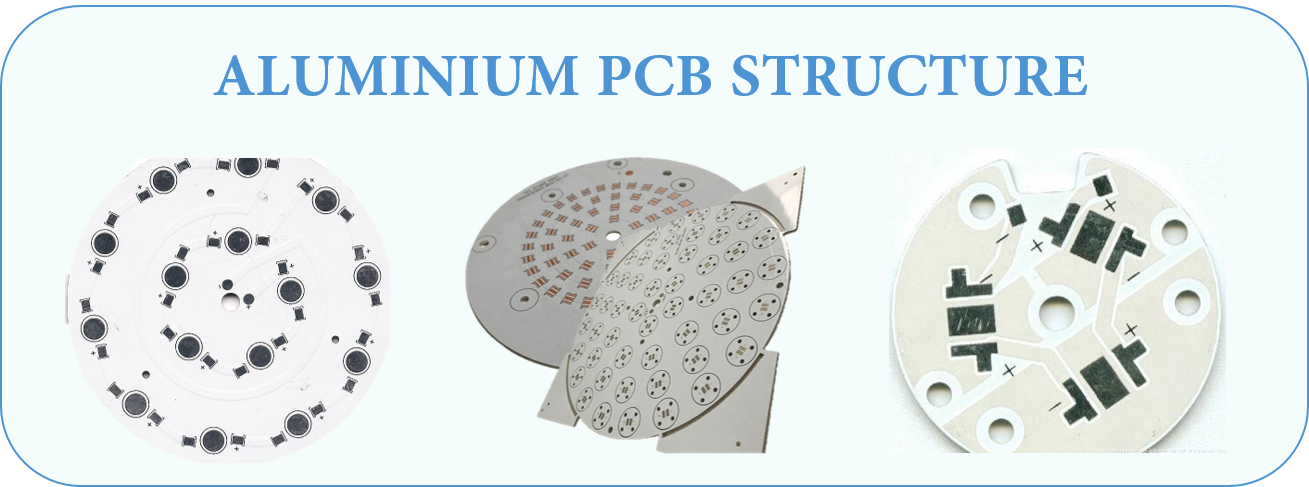
AluminumPCBs are actually quite similar to FR4 PCBs. The basic structure of Aluminum PCBs is four layered. It consists of a layer of copper foil, a dielectric layer, an aluminum base layer and aluminum base membrane.

- Copper Foil Layer: the copper layer used is relatively thicker than normal CCLs ( 1oz-10oz). A thicker layer of copper means a larger current carrying capacity.
- Dielectric Layer: the Dielectric layer is a thermally conductive layer and is around 50μm to 200μm thick. It had a low thermal resistance and it suitable for its application.
- Aluminum Base: The third layer isthe aluminum base which is made up of aluminum substrate. It has a high thermal conductivity.
- Aluminum Base Membrane Layer: Aluminum base membrane is selective. It has a protective role by keeping the aluminum surface safe from scraping and unwanted etching. It is of two types i.e. Lower than 120 degree or around 250 degrees (anti high temperature)
ALUMINUIM PCB ADVANTAGES
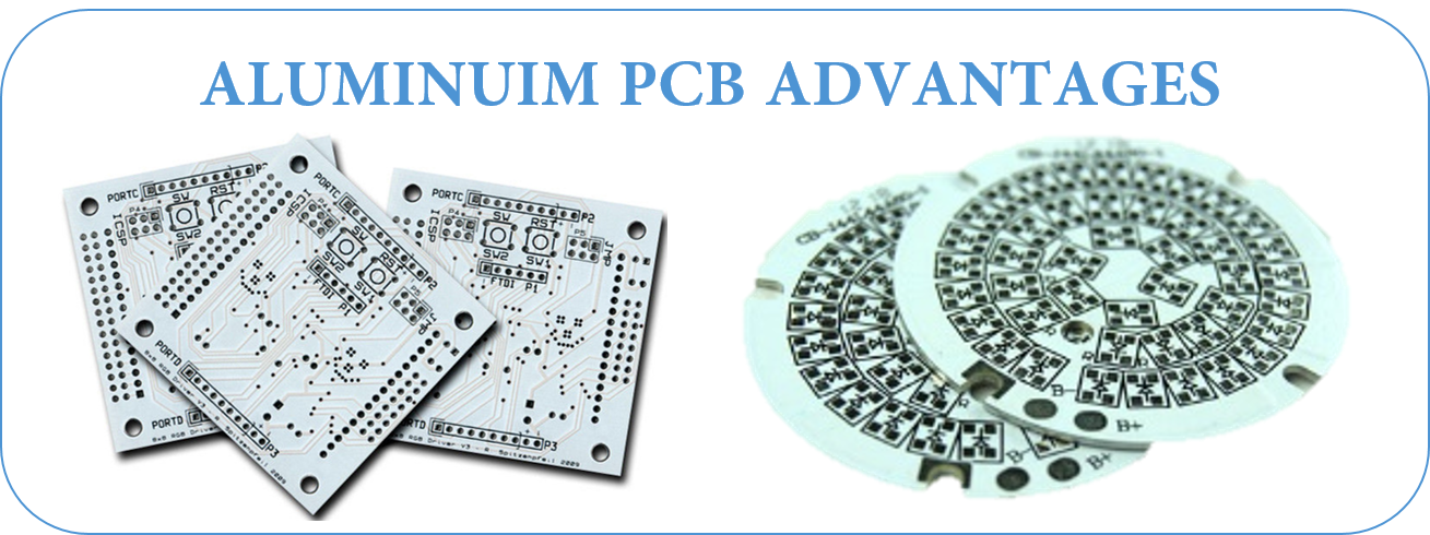
- Low cost: Aluminum is a metal that can be found in a variety of climates, so it is easy to mine and refine. Therefore, the costs of doing so are significantly lower than other metals. In turn, this means that manufacturing products with these metals are less expensive as well.
- Environmentally Friendly: Aluminum is non-toxic and recyclable. Manufacturing with aluminum is also conducive to conserving energy due to its ease of assembly. For printed circuit board suppliers, using this metal helps maintain the health of our planet.
- Heat dissipation: High temperatures can cause severe damage to electronics, so it is wise to use a material that can help dissipate heat. Aluminum can actually transfer heat away from vital components, thus minimizing the harmful effect it could have on the circuit board.
- Higher durability: Aluminum provides strength and durability to a product that ceramic or fiberglass bases cannot. Aluminum is a sturdy base material that can reduce accidental breakage during manufacturing, handling, and everyday use.
- Lightweight: For its incredible durability, aluminum is a surprisingly lightweight metal. Aluminum adds strength and resilience without adding on any additional weight.
- Thermal conductance of dielectic used is 5 to 10 times higher than old epoxy glass.
- Thermal transfer is more efficient and reliable than regular PCB.
ALUMINUM PCB APPLICATIONS
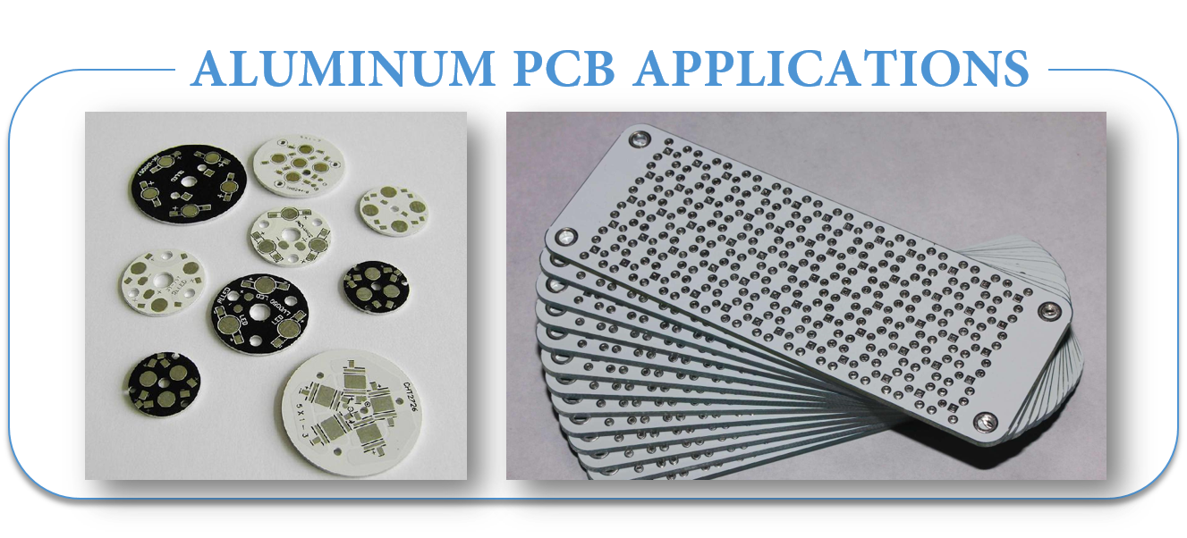
- Audio device: Input, output amplifier, balanced amplifier, audio amplifier, pre-amplifier,power amplifier.
- Power Supply: Switching regulator, DC / AC converter, SW regulator, etc.
- Communication electronic equipment: High-frequency amplifier, filtering appliances,transmitter circuit
- Office automation equipment: Motor drive, etc.
- Automobile: Electronic regulator, ignition, power supply controller, etc.
- Computer: CPU board, floppy disk drive, power supply devices, etc.
- Power Modules: Inverter, solid state relays, rectifier bridges.
- Lamps and lighting: As the advocated promotion of energy-saving lamps, a variety of colorful energy-saving LED lights are well received by the market, and aluminum pcb used in LED lights also begin large-scale applications.
TYPES OF ALUMINUM PCB
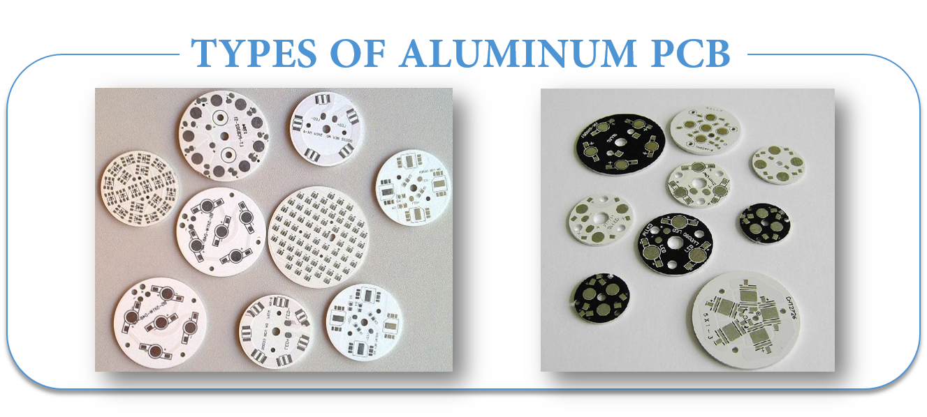
- Flexible Aluminum PCB
It is also a kind of flexible circuit board.
These materials come with polyimide resin integrated with ceramic filters which exhibit high flexibility, thermal efficiency and excellent electrical insulation.
When these materials are applied on an aluminum material, they result in a final product that eliminates the need of costly cable and connectors.
Amount of flexibility allows these products to fold, twist or shape into any form before they remain in place.
Once they adopt a specific shape, they can not be altered or modified like regular flexible PCBs.
- Hybrid Aluminum PCB
In hybrid aluminum construction, non-thermal material is processed and refined separately before it is applied to the thermal materials with aluminum base.
The most common practice is developing 2 layer or 4 layer structure which comprises of FR4 material.
A non thermal material that is bonded with thermal material and aluminum base provides rigidity and helps in the dissipation of heat.
This non thermal bonding is preferred over using all thermal materials because it features less cost and encompasses efficient thermal conductance over regular FR4 products.
No heat sinks or assembly steps are required for the development of this product.
Through hole components can be easily adjusted using component windows on the aluminum base.
This helps in passing the cables and connectors through substrate. Also the seal created by solder fillet eliminates the need of costly adopters.
- Multilayer Aluminum PCB
Multilayer Aluminum PCBs are very common in power supply products and come with multiple layers of thermally conductive dielectrics.
These materials are very useful when they are combined with one or more layer of circuitry in which thermally conductive dielectric is buried between the layers with the help of blind vias which also act as a signal or thermal vias.
Single layer construction of these designs is not very effective, however, when they come with more complex designs they provide an ideal solution for many applications involving heat dissipation.
- Through Hole Aluminum PCB
When it comes to most complex constructions, a single layer of aluminum is back-filled and pre-drilled with before applying lamination, forming a Core of a multilayer constructions.
Thermal bonding materials are then used to laminate the thermal materials on both sides of the aluminum.
Once lamination is done, drilling is applied on the assembly.
In order to maintain proper electrical insulation, the plated through holes created as the result of drilling must pass through aluminum clearances.
ALUMINUM PCB PERFORMANCE
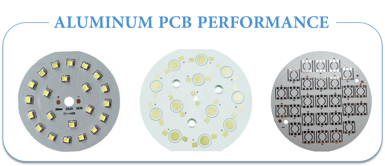
- Thermal Dissipation: the performance of aluminum PCBs while dissipating heat is quite well as compared to ordinary FR4 PCBs. For example, a Fr4 PCB that is 1.5mm thick will have thermal resistance of 20-22 degrees per watt whiles a aluminum PCB 1. 5mm thick will have a thermal resistance of 1-2 degrees per watt.
- Thermal Expansion: each substance has its own coefficient of thermal expansion. The CTE of aluminum (22ppm/C) and copper(18ppm/C)is quite close. Since aluminum PCBs work well in terms of Thermal dissipation they do not have severe expansion or contraction issues. They work excellently and are durable and reliable.
- Dimensional Stability: aluminum PCBs show dimensional stability and stable size. For example, when they are heated from 30-140 degrees, their size only had a change by 2.5%-3.0%.
- Others: Aluminum PCBs can be used in power device surface mount technology. They are effective for use in circuit design because of their performance in terms of thermal expansion of circuit design. They help to prolong products shelf life and product power density. They are also extremely reliable. They can help to shrink the overall volume of the product and is also a cheaper option. They show electromagnetic shielding and high dielectric strength.
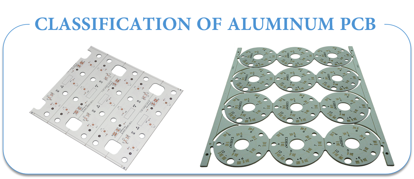
- Universal Aluminum PCB: the dielectric layer used here is made up of epoxy glass fiber pre-preg.
- High Thermal-Conductive Aluminum PCB: the dielectric layer is made up of epoxy resin. The resin used must have high thermal conductivity.
- High-frequency Aluminum PCB: the dielectric layer is composed of polyolefin or polyimide resin glass fiber pre-preg.
MANUFACTURING DIFFICULTIES OF ALUMINUM PCB
The manufacturing process for nearly all aluminum PCBs is essentially the same. Here we will discuss the major manufacturing processes, the difficulties and their solutions.
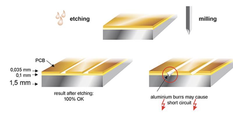
- Copper Etching: the copper foil used in Aluminum PCBs is comparatively thicker. If the copper foil is over 3oz however, the etching requires width compensation. If it is not according to the demand of the design, the trace width will be out of tolerance after etching. Therefore the trace width compensation should be designed accurately. The etching factors need to be controlled during manufacturing process.
- Solder Mask Printing: due to the thick copper foil there is a difficulty in solder mask printing of aluminum PCB. This is because if the trace copper is too thick then the image etched will have a large difference between trace surface and base board and solder mask printing will be difficult. Therefore, the two-time solder mask printing is used. The solder mask oil used should be of good quality and in some cases the resin filling is done first and then solder mask.
- Mechanical Manufacturing: the mechanical manufacturing process involves mechanical drilling, molding and v-scoring etc. which Is left on internal via. This tends to reduce electrical strength. Therefore, the electric milling and professional milling cutter should be utilized for low-volume manufacturing of products. The drilling parameters should be adjusted to prevent burr from generating. This will help your mechanical manufacturing.
Key Requirements When Selecting an Aluminum PCB Manufacturer
For the most part, all PCB Manufacturing follows the same production process regardless of where they are made. The only true differences in suppliers is the level of automation in their process, the newest technology and equipment, and having specific equipment designed to focus on certain types of end products.
For aluminum PCBs, there are several key items that a PCB manufacturer needs to consider if they are going to be able to effectively produce aluminum PCBs in any quantity, including:
- Dedicated Imaging Equipment
Many of our aluminum backed PCBs go into LED applications that are much longer than the standard 18" x 24" or 20" x 24" production panels used in traditional PCB manufacturing. To be able to accurately register and economically produce these parts, a manufacturer must have either a custom piece of 60" wide UV light imaging equipment or a setup capable of screen printing (at one time) an image and then UV curing through an oven.
The old manufacturing process of screen printing half the image and then trying to hand register the first image while screen print the second half is much less effective.
- Specialized Scoring Equipment
The more common equipment that can V score through traditional FR-4 materials is not suited to manage aluminum PCBs. To get the lowest cost possible, we need to get the best yield possible, which means we need to be able to place these parts as close as possible to each other on the production panel. Without V scoring, you must mechanically rout the parts out, which could result in up to 20% loss of your yield, subsequently increasing cost.
Our engineering team has many years of experience helping our customers design arrays that are the most cost effective for them to depanelize.
- Greater Than 40-ton Punch Presses
For aluminum PCBs that are round or have unique features – (slots, large holes, cutouts, etc.) – you will want a manufacturer that can punch out these features. Trying to mechanically rout aluminum PCBs is a very costly way to get these features done in a production environment.
- In-Line Hi-Pot Test
A unique requirement of aluminum PCB is that customers want to know that the product they are getting has passed a hi-pot test. While most PCB manufacturers can do this, it is usually a separate process in a lab that is not located in electrical testing. Epec`s electrical test set up includes a hi-pot test, which dramatically reduces cost for the customer.
The following table presents some of our Aluminum Core materials:
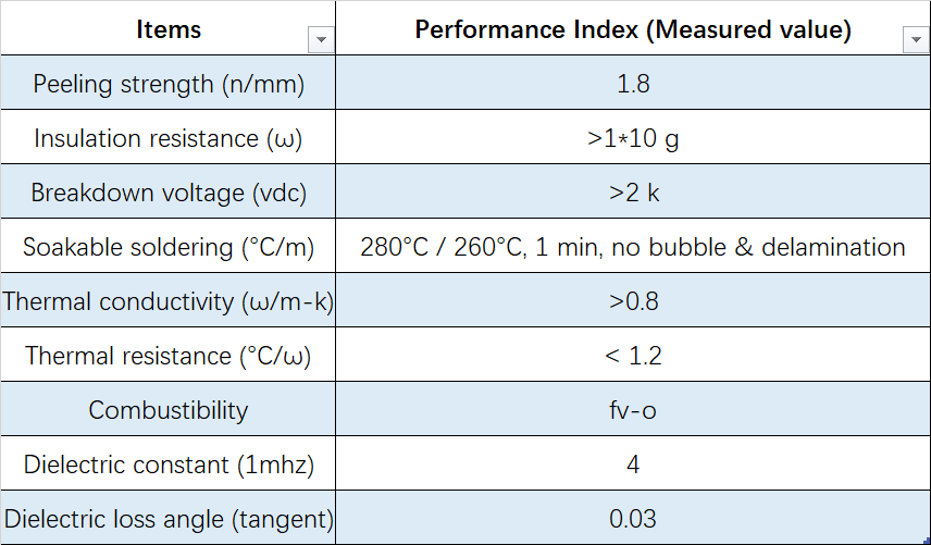
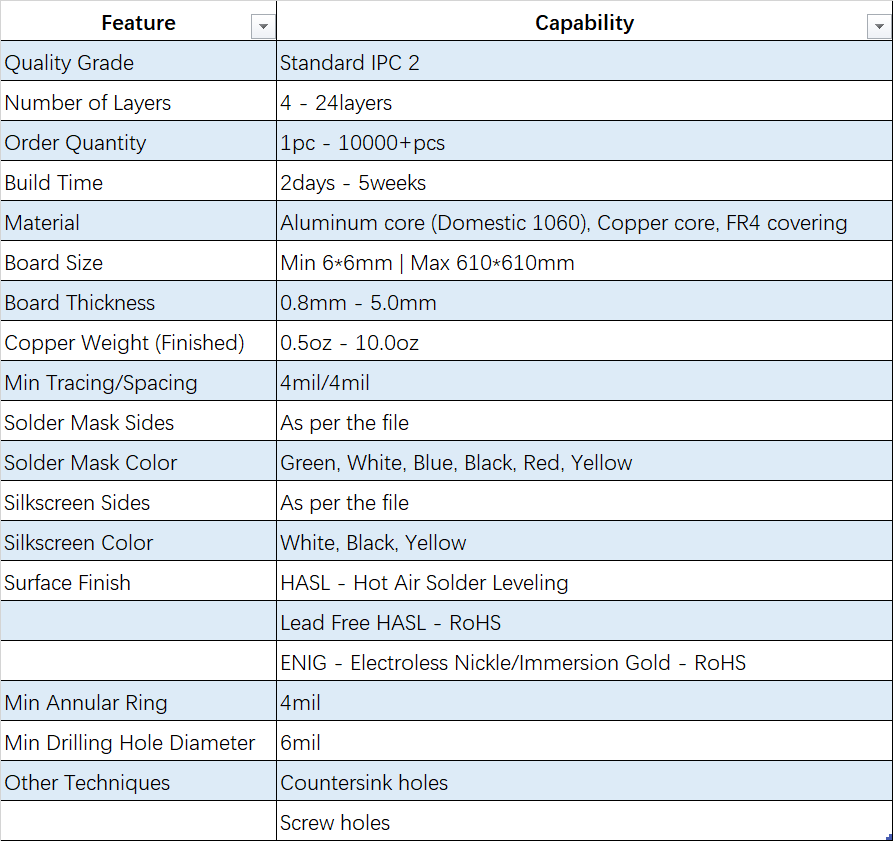
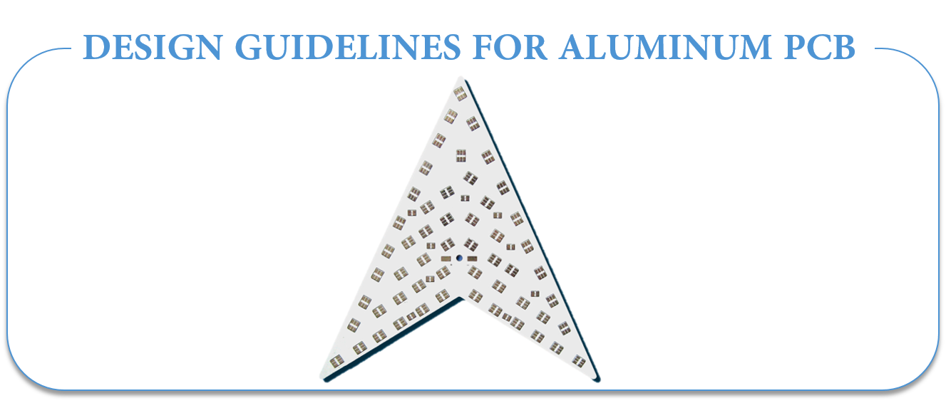
The most important criteria for this is the minimum distance for drill holes required for this type of PCB.
Drilling distances and diameters
In case of double-sided aluminium-core circuits, the aluminium core must be insulated against throughplating. This is done using an excess of resin when press-moulding the aluminium core with prepregs and copper or by plugging. To this end, the aluminium core must be pre-drilled.
The smallest drilling diameter in the aluminium core is 1,0 mm, the smallest final diameter in the PCB is 0,3 mm. So that the drills are not damaged in these close-set drill holes, a minimum spacing of 1,2 mm is required. This is generally the knock-out criteria for a densely-packed control unit.
Variants of aluminium core circuits
- Single-sided PCBs on aluminium carriers
Normally, this variant only has drill holes for fastenings.
- Multilayer PCBs with aluminium core
Copper foils are laminated onto both sides of an aluminium core using prepreg. The PCB can be through-plated. This means that it is also possible to produce multilayers with a 0,5 mm aluminium core.
- PCBs on metal heat-conducting sheets
Completed PCBs are press-moulded to an aluminium carrier using a prepreg. Benefit: Multilayers can also be used (only single-sided SMD). Partial aluminium carriers are possible. Disadvantage: Poor heat dissipation, as the heat has to be dissipated through the entire PCB.
- Aluminium-flex
One further possibility is a rigid- Flex PCB structure, where the aluminium carrier works as the rigid area of the PCB. This means that it is also possible, for example, to connect a control unit as a plug connector over the exposed flex area.
BASICS OF HEAT TRANSFER
At a basic level, a discussion about heat transfer includes two topics: temperature and heat flow. Temperature represents the level of thermal energy that`s available, while heat flow represents thermal energy movement from one place to another.
Microscopically, thermal energy is directly related to a molecule`s kinetic energy. The greater the temperature of a material, the greater the thermal agitation of its molecules. It`s normal for areas that contain a lot of kinetic energy to pass it along to areas with less kinetic energy.
There are some material properties that effectively modulate heat that`s transferred between two areas at different temperatures. These include thermal conductivities, material densities, fluid velocities and fluid viscosities. Together, these properties make resolving many heat transfer problems pretty complicated.
THE MECHANISMS OF HEAT TRANSFER
Heat transfer mechanisms can be grouped into three broad categories:
- Conduction. Areas that have more molecular kinetic energy will send their thermal energy to areas that have less molecular energy. This occurs through a direct collision of molecules, known as conduction. In metals, some of the energy transported from one area to another is also carried by conduction-band electrons.
- Convection. When heat is generated in an electronic device, it`s transported via conduction to an area
- where it is then transferred to a fluid. That process is convection, and the fluid can take the form of a gas such as air or conventional water.
- Radiation. All materials give off thermal energy in amounts that are determined by temperature. When the temperatures are uniform, the radiation flux is in in equilibrium between objects, and there is no exchange of thermal energy. This balance changes when temperatures vary and thermal energy is transported from areas of higher temperatures to those of lower temperature.
HELP RESOURCES
LED Aluminum PCB Board
Quick Turn Aluminum PCB
Aluminium PCB Board for LED
Aluminium Base Metal Core PCB
Aluminum PCBs vs. Standard PCBs
Round Aluminum Base LED PCB Board
Metal Core PCB Manufacturing Capability
Using aluminium in Flexible Circuits Board
Things You Need To Know About Aluminum PCBs
PCB industry cut into LED PCB heat sink aluminum substrate
Aluminum PCB
Aluminum PCB,Aluminum PCB Led,Aluminum Core PCB,Aluminum Circuit Board
JingHongYi PCB (HK) Co., Limited , http://www.pcbjhy.com