In recent years, with the popularization of wireless communication products and the development of ultra-wideband technology, people have put higher and higher requirements on the bandwidth of antennas. Since 2002, the Federal Communications Commission (FCC) has passed a resolution allowing the 3.1-10.6 GHz band to be used in the commercial field. UWB communication systems with high data transmission rates, low cost, low power consumption and strong anti-interference ability are available. It has developed rapidly. The antenna applied to the terminal of the UWB communication system must have the following characteristics: linear phase response, omnidirectional radiation pattern, and smooth gain. Therefore, the design of ultra-wideband antennas has become one of the main challenges of UWB systems. Planar printed antennas, such as rectangular, circular, elliptical, butterfly monopole, dipole, etc., have the advantages of wide frequency band, low dispersion, low loss, low profile, light weight, easy to manufacture, and low price. Widely used in UWB communication systems. The planar printed antenna with CPW feeding has the advantages of easy serial connection with active and passive components, easy integration of MMIC, and favorable for impedance matching and gain enhancement. However, this band includes the operating bands of WLAN 5.2 GHz and 5.8 GHz. In order to avoid interference with WLAN, it is necessary to add band-stop characteristics in the frequency band of 5-6 GHz. Therefore, UWB antennas with band-stop characteristics have received extensive attention.
In this paper, a planar monopole UWB antenna with band-stop characteristics is proposed, which is simple in structure and novel coplanar waveguide feeding. The antenna is opened with a rectangular wide slit on the radiating element, and then a rectangular microstrip tuning branch is added to obtain good band resistance characteristics. The operating characteristics of the antenna are studied by simulation. The results show that the working frequency band of the antenna is 2.49~14.53 GHz, and the band impedance is good in the 5-6 GHz band. At the same time, it has a good omnidirectional radiation pattern in the whole working frequency band, and thus has certain use value.
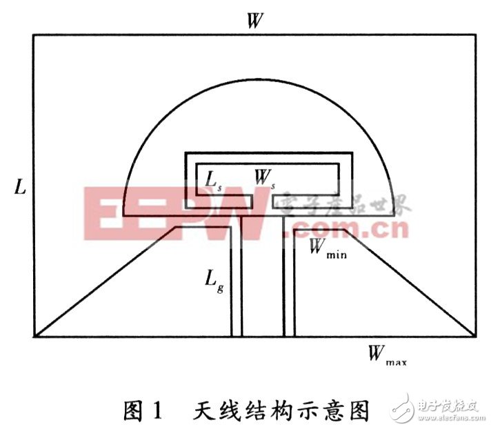
1 Antenna principle and structural designThe structure of the antenna, as shown in Figure 1, the antenna is fabricated at a relative dielectric constant of

1.1 Calculation of the initial structure of the antenna
For a unipolar microstrip antenna, the resonant frequency of the low point, that is, the frequency point of the first 2 VSWR, can be calculated by the cylinder approximation method. In this paper, the equivalent conversion of the square radiating patch is used to derive the relationship between the low-point resonant frequency and the radius of the semi-circular radiating patch.
![]()
Available

Generally L is taken as
![]()
The parameter F is written as

Available from formula (3), formula (4)

So the low frequency fL can be written as

Area equivalence principle ![]() And suppose W=L, then get
And suppose W=L, then get

The unit of fL is GHz; the unit of L, R, r is mm. Using the low-point resonance frequency fL=3.1 GHz of the UWB communication system, the initial radius R of the monopole antenna is calculated to be 15.8 mm. This radius is used for HFSS modeling simulations, which can then be used to achieve larger bandwidths and higher gains by changing the radius.
1.2 Antenna stop band characteristics design
Since the patch current is mainly concentrated in the lower half of the grounding plate, in order to obtain the band-stop characteristic, it is found through optimization of the simulation software parameter analysis that the rectangular slit is opened at a distance of 1 mm from the bottom edge of the radiation patch and the tuning branch is added, and the tuning is performed. The distance between the branch and the radiating element is 0.5 mm and is connected by a microstrip line with a width of 1 mm. The rectangular tuning branch has a length Ls and a width Ws. The basic principle is to introduce an "LC resonant circuit" in the antenna structure that needs to suppress the frequency. By changing the length and width of the microstrip branch, it is equivalent to changing the LC value of the loop, thus affecting the center frequency and corresponding need to suppress. The stopband bandwidth. Through the software simulation, the rationality of this structure is verified, which is equivalent to the introduction of the band-stop filter at the corresponding frequency, which makes the impedance characteristics of the antenna at the center frequency worse.
2 Antenna optimization and parameter analysisThe performance of the antenna was analyzed using the electromagnetic simulation software HFSS to determine the basic dimensions of the antenna. In order to achieve the miniaturization and ultra-wideband characteristics of the antenna structure, the basic dimensions of the final antenna determined by simulation optimization are: the overall antenna size W&TImes; L=50&TImes; 35 mm2, the width of the lower side of the ground plate Wmax=22.67 mm, the ground plate side Width Wmin=3 mm, grounding plate height Lg=16 mm, distance between radiating patch and grounding plate s=0.8 mm.
2.1 Analysis of the working frequency band of the antenna
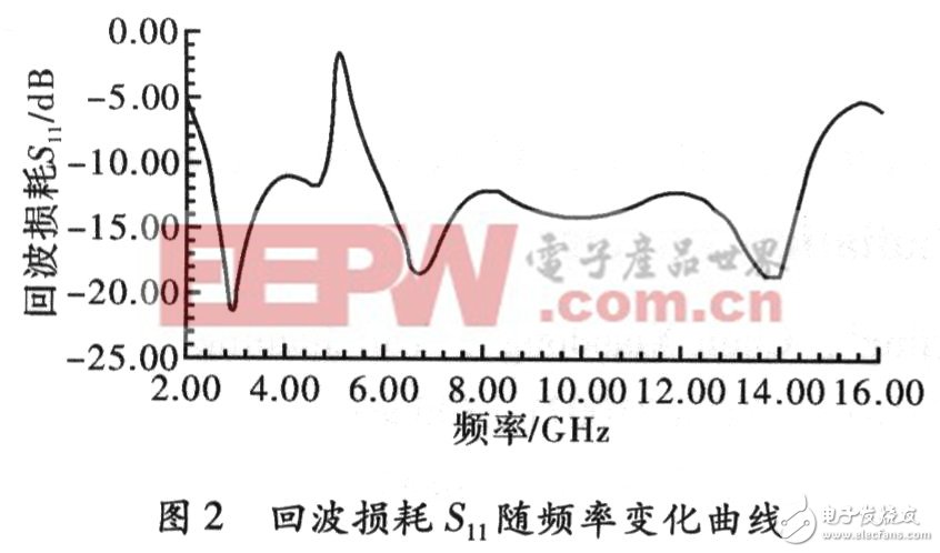
In order to suppress the interference of the WLAN system, the antenna has a notch characteristic by adding a rectangular tuning branch to the radiating metal piece. Since the current of the radiating element is mainly distributed along the edge of the patch, and the current of the grounding plate is concentrated on the upper edge of the grounding plate, a rectangular slit is opened at a distance of 1 mm from the bottom edge of the radiating patch, and a tuning branch is added. The simulation results of the antenna return loss with frequency change, as shown in Figure 2, can be seen that the antenna has a return loss of S11 ≤ -10 dB in the range of 2.49 ~ 14.53 GHz, but at 4.9 ~ 5. The antenna return loss S11"-10 dB in the 92 GHz band indicates that the antenna has band-stop characteristics, which reduces inter-system interference.

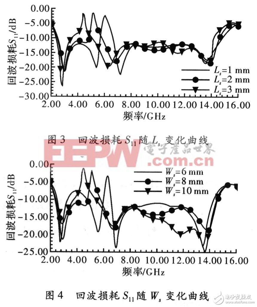
In this paper, the main parameters affecting the performance of the antenna are analyzed. When the other parameters are kept unchanged, the length and width of the tuning branch are changed respectively to make different changes in the return loss. Figure 3 shows the return loss as a function of the length of the tuning branch. It can be seen that when the length is gradually increased, the center frequency of the stop band will move to the lower end of the frequency, and the stop band frequency width is Ls = 1 mm, 2 The mm is basically unchanged, and the band gap bandwidth is significantly increased if the length of the branch is further increased.
It can also be seen from Fig. 3 that the influence of the length of the tuning branch on the high-end frequency of the overall operating band, as the length increases, the high-end frequency decreases and the bandwidth decreases. The return loss of the input end of the antenna varies with the width of the tuning branch. As shown in Figure 4, as the width of the tuning branch increases, the center frequency of the stop band gradually decreases, and the stopband bandwidth is also significantly widened. The overall operating band has little impact. This is mainly because the change in width does not significantly change the current flow of the radiating patch. It can be seen that the required stopband bandwidth range can be achieved by optimizing the length and width of the tuning branch.

2.2 Antenna radiation pattern
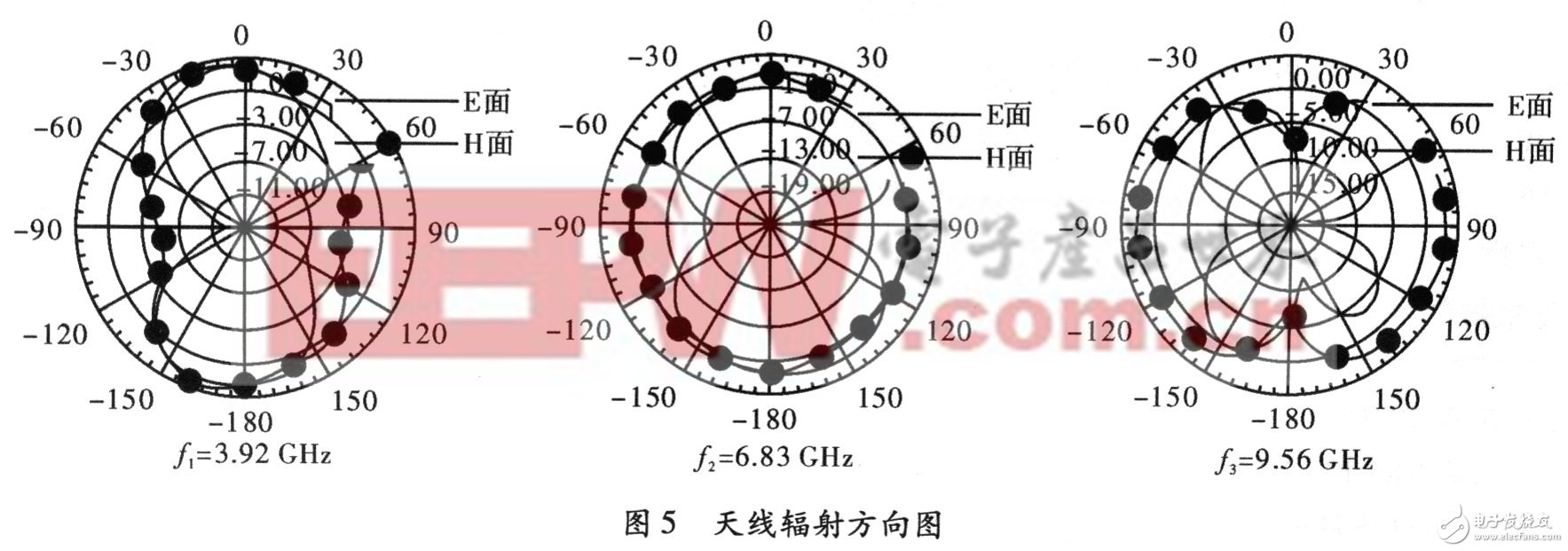
Due to the practical use of ultra-wideband communication technology, the antenna is required to have omnidirectional radiation characteristics on one plane, and the impedance bandwidth is not necessarily the bandwidth of the pattern. Therefore, the simulation analysis of the radiation pattern of the antenna is carried out. Figure 5 shows the radiation pattern of the E-plane and H-plane of the antenna at f1=3.92 GHz, f2=6.83 GHz, f3=9.56 GHz. It can be seen from the figure that the pattern of the E plane at the high frequency end is distorted due to the addition of the tuning branch, but it is relatively stable throughout the working frequency band. The H-plane pattern is almost omnidirectional in the required 3.1 to 10.6 GHz band, and almost no side lobes appear. The results show that the antenna has a stable pattern in the operating band of ultra-wideband communication. .

In this paper, a novel CPW feed is proposed, which has a UWB antenna with band-stop characteristics. By opening a rectangular wide gap on the patch and then adding a rectangular tuning branch, the electromagnetic interference with the WLAN system is successfully suppressed. The antenna has an optimized operating bandwidth of 2.49 to 14.53 GHz, a stopband characteristic of 4.9 to 5.92 GHz around 5 GHz, and a relatively stable omnidirectional radiation direction over the entire operating frequency band. Figure. The antenna has a flat printed structure, low profile, small size, and easy integration with active passive circuits. Therefore, it is a UWB antenna with good performance and certain value in use.
Solar home energy storage power supply
SHENZHEN CHONDEKUAI TECHNOLOGY CO.LTD , https://www.szsiheyi.com