This paper proposes a metal-resistant UHF RFID tag antenna for multi-standard UHF RFID systems. Radio Frequency Identification (Radio Frequency IdenTIficaTIon, RFID) is a technology that uses wireless radio frequency for non-contact two-way data communication to achieve target recognition and exchange of data. The PC remotely controls the reader through the RS 232 interface. After receiving the command, the reader sends an RF command through the antenna to implement the operation of the tag and receive the data returned by the tag. The electronic tag receives energy from its internal antenna and is controlled by the chip (IC) to receive and transmit data.
The frequency bands used by domestic RFID systems are mainly divided into low frequency (below 135 kHz), high frequency (13.56 MHz), ultra high frequency (UHF) (860 to 960 MHz) and microwave (above 2.4 GHz). Wait a few big classes. More and more research is currently focusing on the research of UHF RFID systems. Since the electromagnetic wave is reflected by the metal, the common electronic label cannot be correctly recognized on the metal surface. This shortcoming severely limits its wide application in the logistics industry. Therefore, the metal resistance of the UHF tag antenna has become a research hotspot and a difficult point to overcome. Based on the analysis of the effect of metal on the electromagnetic field of tag antenna, this paper proposes a UHF RFID passive tag antenna with relatively low cost for metal environment. The antenna combines a circular microstrip with a dipole structure to achieve high gain characteristics in a metallic environment. The antenna area of ​​100 mm x 40 mm meets the requirements of a small-sized metal environment and is cost-effective.
1 Effect of metal on tag antenna
The working principle diagram of the RFID system is shown in Figure 1. To study the effect of a metal object on a tag antenna, first consider the characteristics of the electromagnetic field of the metal surface when the antenna is close to the metal. According to the electromagnetic induction theorem, the magnetic field distribution near the metal surface will be "distorted", the magnetic field lines tend to be flat, and the magnetic field is almost parallel to the metal surface in a very close area, so that the magnetic field near the metal surface only has a tangential component without The normal component, so the antenna will not be able to obtain the electromagnetic field energy by cutting the magnetic lines of force, and the passive electronic tag will lose its ability to work normally.

On the other hand, when the antenna is close to the metal, the eddy current is generated inside, and the RF energy is absorbed into its own electric field energy, so that the total energy of the original RF field strength is sharply attenuated. The eddy current also generates its own induced magnetic field. The magnetic field lines of the field are perpendicular to the metal surface and the direction is opposite to the radio frequency field and reacts to the magnetic field generated by the reader, causing the magnetic field of the metal surface to be greatly attenuated, so that the label and the reading are made. Communication between writers is blocked. In addition, the metal can cause additional parasitic capacitance, that is, electromagnetic friction caused by metal, causing energy loss, which causes the tag antenna to be detuned from the reader and destroy the performance of the RFID system.
2 UHF anti-metal tag antenna design and analysis
2.1 Antenna design
The performance of UHF passive tags is mainly determined by two aspects: the gain of the tag antenna and the impedance matching between the antenna and the chip. One way to increase the gain is to connect multiple folded dipole structures in parallel, because the extra dipole radiation impedance can improve the antenna efficiency, so this paper proposes to transform a ring in the traditional dipole antenna structure (see Figure 2). The microstrip line gains gain without increasing the antenna area.

The antenna structure is composed of a modified bent dipole radiator and a ring-shaped microstrip line and a rectangular feed ring. The chip is attached to the opening of the rectangular feed ring for excitation, and the energy is sent to the middle by inductive coupling. Partially connected to the bent dipole radiator. The dipole is stepped and bent to shorten the overall length of the antenna, resulting in a compact structure. The antenna structure is shown in Figure 3.

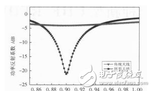
The above two antennas were placed on a 72 mm x 36 mm metal plate, and a dielectric plate with a relative dielectric constant of 4.4 and a thickness of 1 mm was used to simulate with HFSS software, and finally a power reflection coefficient curve was obtained, as shown in Fig. 4. Shown. It can be seen from the figure that the loop antenna proposed in this paper can achieve a power reflection coefficient of -22 dB at a frequency of 900 MHz, and its performance is much better than that of a conventional antenna.
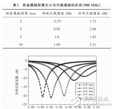
The antenna gain is closely related to its distance from the metal plate. Table 1 lists the gain values ​​of the conventional antenna and the loop antenna at a distance of 2 mm, 3 mm, 5 mm, and 10 mm from the metal plate respectively; The curve of the power reflection coefficient of the antenna at a distance of 2 mm, 3 mm, 4 mm, 6 mm, and 8 mm from the metal plate. It can be seen from Table 1 that the loop antenna gain proposed in this paper is always superior to the conventional antenna when the distance from the metal plate is the same, which verifies the high performance of the loop antenna. At the same time, as the distance from the antenna to the metal plate increases, the gain value shows an irregular trend. Therefore, through a large number of simulation optimizations, it is finally observed that the antenna can obtain the maximum gain and gain when the distance from the metal plate is 3 mm. The value is 2.06 dBi. As can be seen from Figure 5, the loop antenna performs best at 900 MHz.
The ground plane size is another factor that affects antenna performance. Through simulation studies, it is found that the change of the metal surface size has little effect on the resonant frequency, input impedance and bandwidth, but has a great influence on the radiation efficiency and the pattern. The antenna gain is low when operating on a metal surface of 60 mm & TImes; 36 mm, only 1.90 dBi; as the metal surface area increases to 72 mm & TImes; 36 mm, the gain of the antenna is increased to 2.06 dBj, but with The increase in the area of ​​the metal further decreases the gain of the antenna, so that the change in the size of the antenna gain is not proportional to the change in the size of the metal surface, because the radiation direction of the antenna is distorted when the surface area of ​​the metal is increased to a certain extent. So that the radiation field perpendicular to the radiation surface is weakened, and the gain of the antenna will decrease.
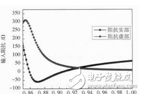
Figure 6 shows the impedance curve of the antenna. It can be seen that the impedance of the antenna is (44.24-j5.96) Ω at 900 MHz. It is necessary to select the chip and antenna with the impedance value of (44.24+i5.96) Ω. Perform conjugate matching. If the chip impedance value used is not (44.24+j5.96) Ω but other capacitive values, the impedance value of the antenna can be optimized by adjusting the slot length of the antenna to achieve conjugate matching between the antenna and the chip.
2.2 Test results
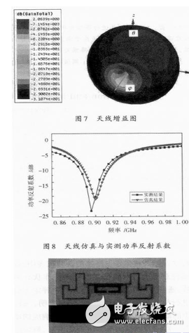
In this paper, Ansoft's HFSS software and Agilent's N5230A vector analyzer were used for simulation and measurement. Figure 7 is the gain diagram of the antenna, and Figure 8 is the simulation and actual measurement results of the antenna. It can be seen that the measured results are in good agreement with the simulation results, which verifies the practicability of the design. The antenna was processed using an FR4 substrate having a relative dielectric constant of 4.4 and a thickness of 1 mm. The physical object is shown in FIG.
3 Conclusion
This paper presents a class of UHF anti-metal passive electronic tag antennas with simple structure and multi-standard compatibility. The antenna utilizes a combination of a circular microstrip line and a dipole structure to achieve high gain characteristics on the metal surface. At the same time, the slot line length can be adjusted to optimize the characteristic impedance of the antenna so that it can be conjugate matched with the chip impedance to improve the Source electronic tag performance. Through experimental analysis, the antenna can obtain a maximum gain of 2.06 dBi at 900 MHz when the area of ​​the metal plate is 72 mm × 36 mm and the distance from the antenna is 3 mm. Finally, based on the simulation analysis, a physical antenna was processed. The actual measurement results are in good agreement with the simulation results, which verifies the effectiveness of the antenna design.
New Products
SHENZHEN CHONDEKUAI TECHNOLOGY CO.LTD , https://www.szfourinone.com