1 Introduction
The main features of white LEDs are: low voltage, small size, high efficiency, environmental protection and long life. At present, the research and development of white LEDs as illumination sources is strong, and new products emerge in an endless stream, and have been actively promoted and applied within a certain range. Compared with conventional mature illumination sources represented by incandescent lamps and high and low pressure gas discharge lamps, although the industry's research on white LED illumination sources is constantly deepening, since white LEDs have a fast response of μs, they can work in DC. And the current-type device under the condition of unidirectional high-frequency pulse current, when used as an illumination source, there is little "inert" illumination of the conventional light source, which may cause a serious problem of light output stroboscopic effect and affect normal use. Paying sufficient attention to the stroboscopic problem of white LED illumination sources under different driving conditions, in order to better meet the requirements of various lighting scenes and obtain a wider range of practical applications.
2 White LED driving and stroboscopic characteristics
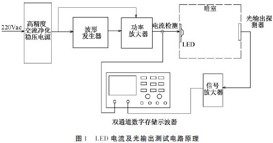
At present, the preparation principle of commercialized and widely used white LEDs is to use blue LEDs to excite yellow fluorescent powder YAG: Ce to obtain white light output. The efficiency of the white light output is directly related to the light-emitting efficiency of the blue LED, the efficiency of the phosphor, and the matching between them. Since the white LED is a fast-responding current-type device capable of operating under DC and unidirectional high-frequency pulse current conditions, it may cause a serious problem of light output stroboscopic as an illumination device. For the sake of analysis, a test circuit as shown in Figure 1 was built to test the current and light output characteristics of the LED under DC linear and AC mains drive conditions.
(1) DC linear drive
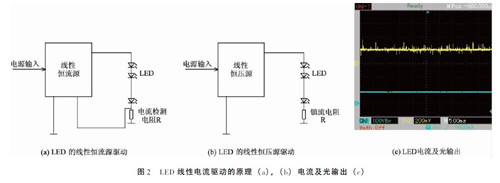
Linear regulator (steady current) power drive is one of the earliest forms of drive [Figure 2 (a), (b)]. Since the LED is a current device, the light output characteristics are directly responsive to the characteristics of the drive current. Therefore, the linear output (steady current) power supply of the LED light output has no stroboscopic phenomenon, which is a smooth straight line. See Figure 2 (c). ) (Figure 2, the upper line is the light output, the lower line is the drive current, the same below).
(2) Power frequency communication mains drive
Due to the universality and economy of AC mains, direct use of 50Hz AC mains to drive LEDs is a more practical driving method. Since the characteristics of the LED must work under unidirectional current (including pulsating current), the circuit configuration of the commercial frequency AC mains drive is to make the forward current flowing through the LED unidirectional and have a constant current. Features, mainly in the following forms:
1) Power frequency AC half-wave drive
The characteristic of power frequency AC half-wave drive is that a single LED flows through a one-way pulsating sinusoidal half-wave current. The specific circuit components are mainly:
A. Diode orientation:
The characteristics of the diode guiding are: using a certain specification of the rectifier diode D for reverse current blocking, so that the current flowing through the LED is a positive pulsating sinusoidal half-wave current, the specific circuit is shown in Figure 3 (a).
B. Diode bypass:
The characteristics of the diode bypass are: Use a certain specification of the rectifier diode D to bypass the reverse current to ensure that the current flowing through the LED is a positive pulsating sinusoidal half-wave current. The specific circuit is shown in Figure 3(b).
C. Dual LED parallel
The parallel connection of the two LEDs is: using the same type of LEDs in reverse parallel, so that they work in the forward and reverse directions of the current respectively, that is, the current is automatically guided, so that the current flowing through the single LED is a positive pulsating sinusoidal half-wave current, which is generally improved. The efficiency of current utilization has doubled the overall light output. The specific circuit is shown in Figure 3 c. The LED current and light output driven by the power frequency AC half-wave are shown in Figure 3d.

2) Power frequency AC full wave drive
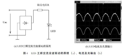
The power frequency AC full-wave drive can improve the light output efficiency of a single LED, mainly by using a full-wave rectifier to convert the power frequency AC current into a one-way pulsed DC, so that the LED flows through a one-way pulsed sinusoidal full-wave current. The specific circuit, current, and light output characteristics are shown in (a) and (b) of Figure 4 (the deadband current present in Figure 4 (b) is due to the minimum turn-on voltage of the LED).
According to the calculation formula of the stroboscopic wave depth of the light source:
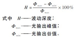
To analyze, whether using sinusoidal half-wave or sinusoidal full-wave AC current to drive the LED, the fluctuation of its light output is very large, and the undulation depth of the stroboscopic wave is as high as 100%, which will lead to poor quality of the illumination source. It is not suitable for the occasions where high-quality lighting is required, so it cannot be used as a mainstream lighting driver. It is just a simple and transitional way.
(3) High frequency switching constant current source drive:
Since the high frequency of the switching power supply can bring a series of advantages and the technology is mature, the current mainstream LED lighting driving method adopts a high-frequency power conversion mode, and the output thereof is a stable current containing a periodic pulsating component. . According to different circuit topologies, the magnitude of the current ripple component of the output is also different. The typical architectures of LED high-frequency constant-current driving power supplies are: buck converters, boost converters (inductive boost and switched capacitors), and buck-boost converters. According to whether the electrical input and output are directly connected, it is divided into two categories: isolated and non-isolated [1]. Due to the different architectures of the circuits, the output current waveforms are varied and varied. In order to categorize the problem, the test circuit shown in Figure 1 is still used to test the LED current and light output characteristics by simulating the current output of the high frequency switching constant current source, and the average value of the forward current flowing through the LED during the test. constant. For this purpose, the high-frequency driving current and light output characteristics of the LED under different waveforms, different frequencies and different output current ripple conditions were tested.
1) Light output under different waveform driving conditions
The test of the LED light output characteristics under different waveform driving conditions is performed by using sinusoidal full-wave (multiplier), pulsating DC, triangular wave and square wave current with a frequency of 30 kHz while maintaining the average value of the driving current. The actual waveform obtained is shown in Figure 5 (a) ~ (d).
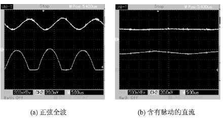
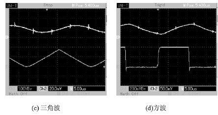
Figure 5 LED light output under different waveform driving conditions
It can be seen from the comparison of Fig. 5 (a) ~ (d): In general, the light output of the LED is well responded to the waveform of the drive current, with stroboscopic effects of different depths. Analyze and summarize as follows:
A. The degree of fluctuation of the light output of the LED is directly related to the degree of pulsation of the drive current. The larger the pulsation component, the greater the fluctuation of the light output, and the more stroboscopic;
B. In the driving of four different waveform currents, the square wave current drive (corresponding to LED running in PWM dimming mode) has the largest stroboscopic depth (> 95%), and the triangular wave current drive is second (~80%), sine The full-wave current drive is again (~ 65%), and the pulsating DC drive is minimal ( < 10%);