This article introduces the STC12C5A60S2 programmable clock module and system power saving module code.
STC12C5A60S2 register introduction


//************************************************ ****************************//
// STC12C5A60S2 programmable clock module
//
//
// Description: STC12C5A60S2 microcontroller has three programmable clock outputs CLKOUT0/T0/P3.4
// CLKOUT1/T1/P3.5, CLKOUT2/P1.0
//
// related registers: AUXR (auxiliary register), WAKE_CLKO (clock and system power-down wake-up control register
Device)
// BRT (Independent Baud Rate Generator Timer Register)
//
// Program description:
// This program can optionally implement P3.4 output CLKOUT0 clock, P3.5 output CLKOUT1
bell
// P1.0 output CLKOUT2 clock
//
////********************************************** ******************************/
/
#include 《STC12C5A60S2.H》
#include "intrins.h"
//#define Port_BRT //If you want to test the independent baud rate generator clock output, please open this sentence
/ / If you want to test CLKOUT1 and CLKOUT0 please comment this sentence
#ifdef Port_BRT /* Condition Compilation Independent Baud Rate Generator Clock Output*/
//*********************************//
// CLKOUT2 clock initialization //
//*********************************//
Void CLKOUT_init(void)
{
WAKE_CLKO = 0x04; //Bit2-BRTCLKO allows P1.0 to be configured as an independent baud rate generator
Clock output
//Output frequency when BRT works in 1T mode = Sysclk/(256-BRT)/2
//BRT works when it is working in 12T mode = Sysclk/12/(256-BRT)/2
AUXR = 0x14; //Bit4-BRTR allows independent baud rate generator operation
//Bit2-BRTx12 BRT works in 1T mode
BRT = 0xff; //Change the value of this register to divide the clock frequency of the output
}
#else /* Condition Compile CLKOUT0 Clock Output*/
//*********************************//
// CLKOUT0 clock and CLKOUT1 initialization //
//*********************************//
Void CLKOUT_init(void)
{
WAKE_CLKO = 0x03; //Allow P3.4/T0 pin to be configured as timer 0 clock output CLKOUT0
//T0 output frequency in 1T mode = SYSclk/(256-TH0)/2
//T0 output frequency when working in 12T mode = SYSclk/12/(256-TH0)/2
//1T means 1 for every 1 clock, 12 times that of normal C51
//12T means that every 12 clocks plus 1 is the same as ordinary C51.
//Allow P3.5/T1 pin to be configured as timer 1 clock output CLKOUT1, only
Can work in timer mode 2
//The output frequency of T1 when operating in 1T mode = SYSclk/(256-TH0)/2
//T1 output frequency when working in 12T mode = SYSclk/12/(256-TH0)/2
//1T means 1 for every 1 clock, 12 times that of normal C51
//12T means that every 12 clocks plus 1 is the same as ordinary C51.
AUXR = 0xc0; //T0 timer speed is 12 times that of ordinary 8051, that is, working in 1T mode
/ / T1 timer speed is 12 times that of the ordinary 8051, that is, working in 1T mode
TMOD = 0x22; //Timer 0 working mode is mode 2, automatic loading time constant
/ / Timer 1 working mode is mode 2, automatic loading time constant
TH0 = 0xff; //Change the value of this register to divide the clock frequency of the output
TL0 = 0xff;
TH1 = 0xff; //Change the value of this register to divide the clock frequency of the output
TL1 = 0xff;
TR1 = 1;
TR0 = 1;
}
#endif
//**********************************//
// main program //
//**********************************
//
Void main()
{
CLKOUT_init();
While(1);
}
//************************************************ ****************************//
// STC12C5A60S2 system clock module
//
//
// Description: STC12C5A60S2 microcontroller has two clock sources, internal R/C oscillation clock and external crystal
bell
// The factory standard configuration uses an external crystal or clock
//
//
// involved register: CLK_DIV (clock divider register)
// The clock source can be 0, 2, 4, 8, 16 by the combination of Bit0-2 of this register.
// 32, 64, 128 crossover
// //
// Program description:
// Divide the external clock to get Sysclk, then pass the independent baud rate of P1.0
// Clock output function Sysclk/2 output clock frequency
//************************************************ ****************************//
#include 《STC12C5A60S2.h》
#include "intrins.h"
#define Bus_clk 12 //If you want to modify the system clock, modify it directly here.
//12 is 12M sysclk
//6 is 6M sysclk
//3 is 3M sysclk
//1500 is 1.5M sysclk
//750 is 750kHz sysclk
//375 is 375kHz sysclk
//187500 is 187.5kHz sysclk
//93750 is the sysclk of 93.75kHz
//*********************************************//
// System clock initialization //
//*********************************************//
Void Sysclk_init(void)
{
WAKE_CLKO = 0x04; //Configure P1.0 port as frequency output
AUXR = 0x14; //Allow baud rate clock to work
//Work mode is 1T
BRT = 0xff;
#if( Bus_clk == 12 )
CLK_DIV = 0x00;
#elif( Bus_clk == 6 )
CLK_DIV = 0x01;
#elif( Bus_clk == 3 )
CLK_DIV = 0x02;
#elif( Bus_clk == 1500 )
CLK_DIV = 0x03;
#elif( Bus_clk == 750 )
CLK_DIV = 0x04;
#elif( Bus_clk == 375 )
CLK_DIV = 0x05;
#elif( Bus_clk == 187500 )
CLK_DIV = 0x06;
#elif( Bus_clk == 93750 )
CLK_DIV = 0x07;
#endif
}
//**********************************************//
// main program //
//**********************************************//
Void main()
{
Sysclk_init();
While(1);
}
//************************************************ ****************************//
// STC12C5A60S2 system power saving module //
//
// Description: The STC12C5A60S2 microcontroller has three power-saving modes to reduce power consumption. Idle mode, low speed mode
// power down mode
//
//
// involved register: PCON (power control register)
// Bit0 - IDL controls the microcontroller to enter IDLE idle mode
// Bit1 - PD controls the microcontroller to enter power-down mode
// //
// Program Description: The program implementation allows the MCU to work for a while (displayed by the P0^3 indicator)
// Then enter the power-down state, use the external interrupt 0 to wake up the microcontroller
// After wake-up, the MCU will start working by flashing the P0^0-3
////********************************************** ******************************/
/
#include 《STC12C5A60S2.h》
#include "intrins.h"
#define uchar unsigned char
#define uint unsigned int
Uchar Power_Down_Flag = 0; //Enter the power down status flag
Sbit Chip_Start_LED = P0^0; //Microcontroller starts working indicator
Sbi
t Power_Down_LED_INT0 = P0^1; //INT0 port power-down wake-up indicator
Sbit N_Power_Down_LED_INT0 = P0^2; //INT0 port has no wake-up indicator
Sbit Normal_Work_LED = P0^3; // normal working indicator
Sbit Power_Down_Wakeup_INT0= P3^2; //Outer interrupt wake-up input
Void Delay_ms( uint time );
Void Normal_work(void);
Void Intp_init(void);
Void After_Powr_Down(void);
//***********************************//
// software delay //
//***********************************//
Void Delay_ms( uint time )
{
Uint t; //delay time = (time*1003+16) us while(time--)
{
For( t = 0; t " 82; t++ );
}
}
//***********************************//
// normal work instructions
//***********************************//
Void Normal_work(void)
{
Normal_Work_LED = 1;
Delay_ms(500);
Normal_Work_LED = 0;
Delay_ms(500);
}
Void After_Power_Down(void)
{
Uchar i ;
For( i = 0; i " 100; i++ )
{
P0 = 0x0f;
Delay_ms(500);
P0 = 0x00;
Delay_ms(500);
}
}
//***********************************//
// interrupt initialization //
//***********************************//
Void Intp_init(void)
{
IT0 = 0; // external interrupt source 0 is low trigger
EX0 = 1; //Allow external interrupts
EA = 1; //open total interruption
}
//***********************************//
STC12C5A60S2 microcontroller module code 13_stc12c5a60s2
// main program //
//***********************************//
Void main()
{
Uchar j = 0;
Uchar wakeup_counter = 0; //record the number of power failures
P0 = 0x00;
Chip_Start_LED = 1; //The microcontroller starts working
Intp_init(); //External interrupt 0 initialization
While(1)
{
P2 = wakeup_counter;
Wakeup_counter++;
For( j = 0; j " 250; j++ )
{
Normal_work (); / / system normal work instructions
}
Power_Down_Flag = 1; //The system starts to enter the power down state
PCON = 0x02;
_nop_();
_nop_();
_nop_();
_nop_();
After_Power_Down(); //After power-down wake up
}
}
//**********************************//
// interrupt service
//**********************************//
Void INT0_Service(void) interrupt 0
{
If( Power_Down_Flag ) //Power-down wake-up status indication
{
Power_Down_Flag = 0;
Power_Down_LED_INT0 = 1;
While( Power_Down_Wakeup_INT0 == 0 )
{
_nop_(); //wait high
}
Power_Down_LED_INT0 = 0;
}
Else // no power down state
{
N_Power_Down_LED_INT0 = 1; //not power-down wake-up indication
While( Power_Down_Wakeup_INT0 == 0 )
{
_nop_();
}
N_Power_Down_LED_INT0 = 0;
}
}
UL Certified Switches
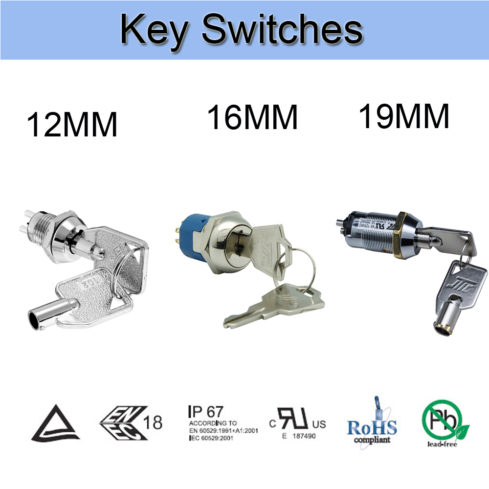
Our UL Certified Switches are mainly 3 Position Key Switch with 19mm Installation size. This series is a representative , competitive and hot product in our products catalog.
UL Certified Electric Key Switch, which indicates the Key Switches that have UL certification. The UL Safety Laboratory is the most authoritative in the United States and the largest private institution in the world for safety testing and identification.

Our company has UL certification testing equipment, so that UL certification series Key Lock Electrical Switches products meet international standard so could meet our customer`s needs. We are devote to supplying high-quality and excellent products to our customers with the Quality management testing, supplier management, feed inspection, in-process inspection, finished product inspection, measurement ,instrument management, final personnel training , high-class quality concepts.
We are always insisted on the quality of the Key Lock Switch, so our key switches with supreme quality could be investigated. If the client receive abnormal quality, the quality team meeting will be held actively to rigorously analyze the cause of the Abnormal product and make the correct solution. The same batch of materials should be separated in time to ensure that similar quality anomalies wont happen again, so we could achieve the goal that corrective and preventive measures are taken to make efficient solutions for the UL series of Key Switches used by customers.

Ul Certified Switches,Ul Certified 16Mm Switch ,Ul Certified Waterproof Switch,Ul Certified Electric Power Switch
YESWITCH ELECTRONICS CO., LTD. , https://www.yeswitches.com