Robust wiring, thermal monitoring and control avoids wire breakage, flame retardance and fire protection, but the design engineering methods required often run counter to intuition.
This article refers to the address: http://
The role of automotive electrical wiring is in addition to connecting power or control and sensor signals from one point in the car to another, one of which is the wiring of the seat heater. Failure to do so may result in the seat not heating or causing fire and fire. Designing a heating wire for a seat heater presents many challenges. The primary challenge is mechanical flexibility and temperature control. The two most commonly used materials today are carbon fiber and pure copper wire harnesses.
The insulating material of the wire is fluororesin and enamel. Typically, the wires are sealed in a fiber/foam to create a shell on both sides of the wire and, finally, are typically protected with an adhesive.
Dynamic characteristics of the wire
The occupant needs to slide on the side pad during the entry and exit of the seat. This action produces a progressive friction and scratch on the internal heating wire of the side pad, which induces considerable pressure. People who are warped and moved in the seat will also exert pressure on the wires.
For metal wires, it is logically recommended to use a wire with a large cross-sectional area. The greater the pulling force, the stronger the expansion performance. No solution can be separated from reality.
Pulling is important, but the softness of the wire is equally important. This can be seen in existing seat heaters that use pure copper wire. Such heaters are constructed by a plurality of wires of small diameter that are softer than thick wires having the same resistance; unfortunately, the wire is not simply softened due to being twisted in the machine direction. .
To do this, the design of the wire is adjusted to spirally wrap the wire around the flexible core. This winding method enhances the softness of the wire and greatly improves the dynamic performance of the wire. The performance of spiral wound wires is 10 times better than that of pure wires.
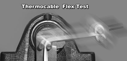
The thermal cable has its own flexible test method (see figure below). The goal of this test is to apply more robust and rigorous testing in the effort to design spiral wound wires, making them suitable for dynamic performance requirements in the field's actual use environment. This test has been added to the International Electrotechnical Commission (IEC) test specification.
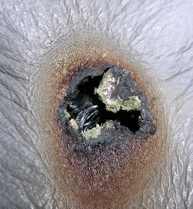
The figure below shows an example of a seat where the wire begins to catch fire. The first step in preventing these seats from catching fire is to improve the simple mechanical ability of the wire to achieve repeated bending without premature breaking. The second step is to accurately monitor the temperature of the wire.
Overheating protection
The heating wire in the existing seat heater can be controlled by a single thermostat. There is no doubt that the "thermal detection area" of a single thermostat is limited, especially where the local hot spot occurs where it is remote from the thermostat.
To simplify overheat protection, a temperature sensing polymer may be used; this temperature sensing polymer will blow at a pre-set temperature that is lower than the combustion temperature of the seat. Traditionally, fuses have been used to create a very low resistance that draws a large amount of current from the Power Supply and burns the premium. However, in order to achieve the resistance required for seat heating, two spirally wound unit wires are added in parallel. In this case, the fuse layer no longer causes an increase in current because the voltage between the two wires is the same as the voltage at each point on each wire.
In order to effectively utilize the fuse layer, the connection between the two wires is temporarily cut off, leaving only the joint of one end of the parallel resistor attached to the power source. If current is monitored to flow through the junction during this time, it should be much smaller than the normal value; in the case of a fusible fuse, if the current drawn is still high, then there is an overheating condition. .
Temperature monitoring
The temperature can be precisely controlled by using a wire that is also a thermistor. Therefore, temperature sensing can be measured on the wire itself. The figure below shows a spiral wound wire (negative temperature coefficient) with an NTC thermistor layer.
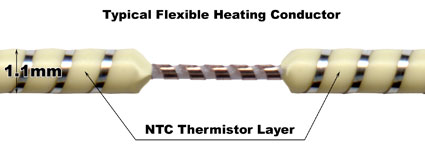
The wire has two heated circuits that are isolated by an NTC thermistor plastic material. The NTC layer has two functions:
1. Monitor the entire temperature
2. Detect hot spots
An important consideration in the design of feedback sensor leads is the long-term stability of the thermistor polymer. It is critical that the electronic circuitry of the control module repeatedly receive a consistent signal from a conductor with narrow band tolerance. This consistency is achieved by processing the thermistor polymer using controlled processing techniques.
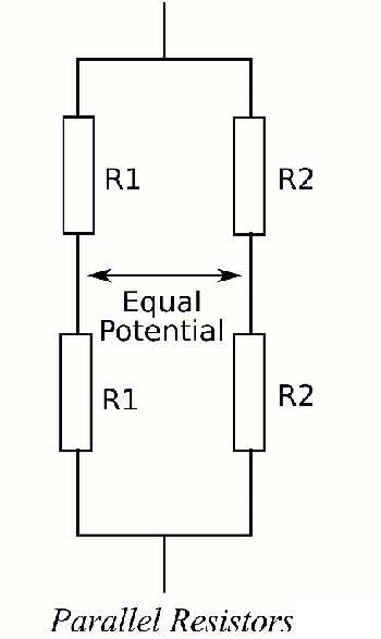
The NTC and PTC (Positive Temperature Coefficient) techniques allow the controller to determine the local area of ​​the superheat and the average element temperature, respectively. However, this technique that relies on temperature changes can cause reproducible and predictable changes in resistance. At low frequencies. The NTC isolation layer can be modeled with multiple parallel resistors as shown in the following figure.
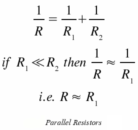
The value of each resistor changes in temperature in the form of an arithmetic function. Therefore, if the two wires are isolated by a layer of NTC material resistance between them, then the resistance between the two wires can be calculated using the following equation:

Where a and b are constants, depending on the amount of NTC material used, the surface area of ​​contact between the wires, the NTC material and the unit length, where T is the temperature of the NTC material. The entire NTC resistance is the reciprocal of the sum of all unit lengths.
When the resistors are connected in parallel, if the resistor has a much lower resistance than the other resistors, then the total resistance can be approximated to the lowest resistance.
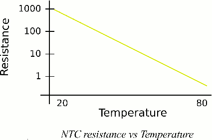
Thus, it can be seen that if the temperature of a portion of the NTC material increases, then the temperature of the entire resistance between the two wires is approximately equal to the resistance of the hottest portion of the NTC material. For short lines of NTC material (i.e., less than 20 m), a small temperature rise of 30 degrees for the unit line (e.g., less than 0.5 m) will have a significant effect on the electrical resistance of the entire NTC material lead. Therefore, by monitoring the resistance of the NTC isolation layer, if the value of the resistance is greatly reduced, the controller can determine the overheated region where the temperature rises locally.
Measuring the resistance of NTC
There are several ways to measure the resistance of an NTC. The advantages are different. When designing this circuit, you need to consider which method to use. First, note that the inherent resistance of NTC materials at very low temperatures is very high, on the order of tens of megaohms; according to Ohm's law, at low voltages (such as 12V in automotive applications) the inherent resistance is equal to the very low current through the isolation layer. For example, if the resistance of the NTC isolation layer is 30 megohms at 20 degrees, then the current flowing through the isolation layer at 12V is 0.4 mA. One way to measure NTC resistance is to use a different amplifier and a small value series resistor with an NTC layer (see figure below). 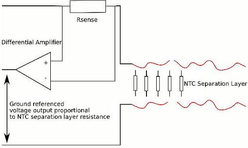
There is also a way to measure the NTC resistance, which is to create an RC filter in which the fixed capacitor is connected in series with the NTC resistor. As the resistance of the NTC layer changes, the transfer function of the filter will change accordingly.
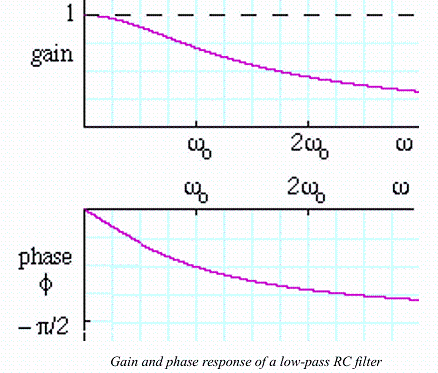
Therefore, for an AC signal of a suitable frequency (when the NTC material operates at 20 degrees, close to the cutoff frequency of the filter), as the temperature of the NTC material increases, depending on the configuration of the filter, the cutoff frequency either goes low or goes high. The AC signal will also be affected by the phase shift, the phase shift, and the temperature dependence. This introduces two methods of measuring NTC resistance.
Measuring the impedance of the PTC
PTC technology uses a special metal material resistance with a known temperature coefficient to calculate the average component temperature. As the temperature of the metal increases, the resistance also increases in a linear relationship. In contrast to the NTC isolation layer, the model of the PTC line consists of a number of resistors connected in series. This has the effect that any overheating in this area will have a negative impact on the entire measured PTC resistance.
The easiest way to measure PTC resistance is to let the PTC wire flow a constant current. As the wire temperature increases, the resistance increases; according to Ohm's law, the voltage across the PTC wire will decrease. The terminal voltage of the PTC wire can be monitored by an analog-to-digital converter on the microprocessor, and then the temperature of the component is calculated based on the monitoring result.
Economic
The overall technology of the above-described thermistor wires and control modules is more competitive than the economics of the existing seat heating technology, and the product design is more robust and safer to use.
Fast Phone Charger,Usb Charger,Usb Battery Charger,Usb Car Charger
Ninghai Yingjiao Electrical Co., Ltd. , https://www.yingjiaoadapter.com