Electronic products are becoming lighter and thinner, and the collection of electronic components is getting higher and higher. The coupling of power supply, grounding noise (Signal) and signalling (Coupling) becomes electronic. The key factors that must be overcome when designing a product.
These are either noises or signals from outside the system, or from the system itself, and interference between the signals (RadiaTIon) or conduction (ConducTIon). If the frequency range is from 30MHz to 1GHz, it is called electromagnetic interference. (EMI, ElectromagneTIc Interference) problem; when it affects the higher frequency radio frequency band (RF), it is also called the radio frequency interference (RFI) problem. In portable products, the RFI problem has more seriously affected the communication quality of the product.
To solve these annoying electromagnetic interference problems, first classify them from a large direction, which can be divided into problems of signal integrity (SI, Signal Integrity) and power integrity (PI, Power Integrity). In the measurement analysis of the practice, the Debug Mode of Near Field measurement and the verification mode of Far Field measurement are used. If the component characteristics and boundary conditions of the product are sufficiently high, simulation software and simulation tools (such as ANSYS, Keysight, CST, etc.) can be used for simulation verification and prediction. To further understand the characteristics of each component in the product under various operations, a time-frequency (TIme-Frequency) numerical analysis method (such as FFT, HHT, enhance-Morlet Transfer, etc.) is also used. In the design practice of products, to solve these problems, it is necessary to use Filter, Moving Resonant Frequency, Spread Spectrum Clock (SSC). . . Waiting for the trick.
Spread spectrum methods, in today's technology has been integrated into integrated circuits (IC, Integrated Circuit), most of the frequency-related integrated circuits will have spread-spectrum design, mainly used to solve the signal frequency online main frequency energy is too strong The problem. Frequency shifting is a more general solution. The main purpose is to remove the problematic frequency pole position from the current frequency range. But how to find the problem rate frequency, most of them can only rely on the simulation tool to find the frequency response (Resonant) point, in order to re-plan the countermeasures (such as adding filter components or changing the line width, line length or direction). However, as can be seen from the analysis notes mentioned above, it is very easy to become the result of GIGO (Garbage In Garbage Out) if the component characteristics and boundary conditions are not complete enough. The use of filters is the most intuitive and straightforward solution. Of course, there is also the meaning of frequency shifting. However, various filters have their own methods and limitations.
When solving EMI/RFI problems, the most commonly used filters are shown in Figure 1. They are low-pass filter devices. The π-type filter (π-Model Filter) is the most efficient and simple filtering device. The commonly used integrated products are divided into CLC and CRC, as shown in Figure 2.
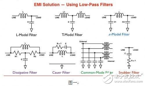
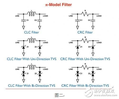
The CLC filter device can choose to minimize the influence on the main frequency attenuation. The most important factor is that when the signal inside the system is being transmitted, when only the high frequency harmonic wave (Homonic) needs to be filtered. The main frequency energy can be kept as small as possible, and the high frequency signal is filtered out. The CRC type filter is mainly used at the interface end of the system, and can have the characteristics of selecting the preferred impedance matching (Impedance Match), thereby effectively reducing the secondary interference problem caused by the impedance mismatch.
Regardless of the filtering device, it is necessary to consider whether the filtered frequency energy is more or less. It is also necessary to consider the skew (Jew) and jitter (Jitter) of the signal to make the decision, so it is not necessary to filter all the high frequency signals. The more you get, the better. There are many times to properly reserve 3x and 5x or even 7x signal energy, which will make the Eye Diagram better. However, in the processing of the differential signal, the signals of the positive and negative ends must be 180 degrees out of phase to obtain the best eye diagram. The even octave harmonics from the power supply and the ground or Common-Mode Noise will cause the distortion of the differential signal. Refer to the signal on the left side of Figure 3.
To solve this problem, the main method is to use Common-Mode Choke, which uses common signals in the inductor signal suppressor to cancel the common mode noise. Three instructions are shown. However, using the Common-Mode Filter device in Figure 3, since the L-Model filtering effect is also seen on the differential mode signal, it is necessary to use the filter device to see the differential mode at the same time. The filtering frequency of the mode, the filtering effect of the two is different. At this point, it can be found that the above two types of filtering devices are used to solve the noise problem on the signal. Moreover, there are many opportunities to be used at the interface end of the product, so the problem of electrostatic discharge cannot be ignored here.
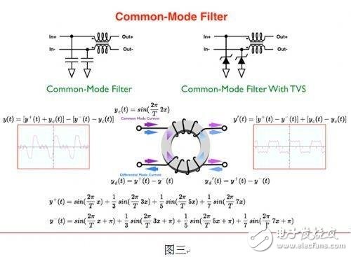
Therefore, Jingyi Technology has integrated its system-level ESD protection technology with these signal filtering products to make a perfect combination. The filtering device including TVS (Transient Voltage Suppressor) in Figure 2 and Figure 3 is used to effectively solve the problem at the same time. Products with static and filtering problems. In addition, when using these filter components, it is no longer the size of the capacitors, but the transmission loss (Insertion Loss) and the reflection loss (Return Loss) of the signal, which is represented in the S parameter. The energy signal can be transmitted or reflected, whereby the information selects the appropriate primary frequency and the intensity to be filtered.
In the power and grounding sections, the small signal return path in the printed circuit board (PCB) is the most important magnetic antenna antenna (EMI) path for EMI radiation. A good multi-layer ground plane design can reduce the return path area, but if only the capacitor without damping effect is used, and the good ground point position cannot be designed in the system, the power will be reversed. The noise is brought to the entire ground plane, causing broadband noise.
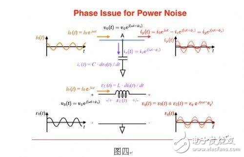
However, if you use an RC snubber (Snubber), you must adjust the RC value to the band that can be filtered, which is another difficult task. On the other hand, due to the internal circuit design of the main function chip, there is a design that requires multiple frequency, frequency division, and the like. Therefore, many of the various odd and even octave small signal energies become noise and the carrier is on the power supply. It is then radiated or conducted to various locations on the PCB via the power and ground design on the system. Under the complicated operation of these numerous integrated circuits, these noise energy is generated. The voltage and current single-frequency signals near the power contact of the main chip are no longer 90 degrees (capacitance or inductance noise reduction) or 0 degrees (resistance characteristics). The phase difference.
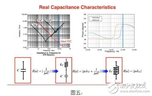
However, under the use of a simple capacitor or inductor, the voltage or current small signal can only do 90 degree phase addition and subtraction. However, when the voltage and current phase difference is no longer 90 degrees or 0 degrees, then the use of capacitors or inductors, sometimes making some single-frequency noise more enhanced, as shown in Figure 4 is a complex superposition effect. In addition, the use of the capacitor must also note that it has a certain range of use frequency, after it exceeds its frequency turning point, it becomes an inductor, as shown in Figure 5. In the vicinity of the frequency return point, there will also be a Pole problem. In order to solve the above problems, Jinghao Technology uses the characteristics of the branch current to design a filter damper chip that can detect the voltage and current small signals in the broadband band range and can adjust the phase difference therebetween. .
In addition to the power supply filtering effect, the energy transmitted from the noise to the ground can also be reduced. It is designed into the size of the capacitor, so that engineers can have the best and convenient choice in addition to the capacitor in the final stage of product development, in order to pursue the time to market. Where can I? The RFI problem in a product is like dealing with power supply noise. Some situations are: RF signals were originally intended for reception, but they are coupled to the power supply and cause some other functional chips to malfunction; others are: some functional chips (such as cameras). The multiplier signal or power supply noise is coupled to the power, signal or antenna of the Base Band or RF IC, causing temporary failure or error in the function of these chips.
To solve the electromagnetic interference problem of portable products, the first step is to make a preliminary analysis of the PI problem. For the layout of the power supply and the grounding, it is better to extract the layers for each power supply and make an overlap check with the ground plane. For some return paths, confirm whether the solution is correct. In addition, for the power supply and grounding layout of the product, it is best to use the simulation tool to confirm the pole position of the Z-Frequency Characteristics, and try to avoid the sensitive frequency band position. Secondly, it is necessary to confirm whether the SI problem (such as Impedance Match, Interconnection Bandwidth, Insertion Loss, Return Loss, Cross Talk, Propagation Delay, etc.) on the product signal has been adjusted, and the problem is confirmed by the measurement tool. A suitable signal filtering device. When dealing with SI problems, if you find some problems with even multipliers, then go back and confirm that they are common mode problems or power and ground parts, check the source, and filter the countermeasures. It can make a perfect layout analysis of the product SI and PI, and fully understand the application characteristics of various filtering devices, and select the correct filter components, so that it can get twice the result with half the effort to solve the electromagnetic interference problem.
The Hydrogel Screen Protector is made of imported material with TPU as the base material and is combined with hydrogel. It has super ductility and retractability, and can perfectly adapt to curved screens and screens with excessively curved edges, so as to fit perfectly without leaving white edges, and basically does not affect the touch experience. It has a strong and effective self-healing function, is impact-resistant, durable, and has better toughness, and has a certain buffering effect on the collision of sharp objects.
The Hydrogel Screen Protector uses glue and hydrogel to activate the stickiness to ensure a perfect fit without warping and leaving blanks, which is more beautiful. The Hydrogel Film is very thin. The responsive, ultra-thin design gives you a bare-bones experience. It's not as thick as a Tempered Glass Screen Protector, so the hydrogel screen protector won't affect the weight and feel of the phone.
In terms of hand feel, the Hydrogel Screen Protective Film has a hydrophobic and oleophobic treatment, so it slides relatively smoothly, and there is no problem in using APP or playing games. In addition, the liquid spilled on it can be slipped off by just tilting it, which is very easy to clean and maintain.
Mobile Screen Protectors,Matte Hydrogel Protector,Anti Blue-Ray Hydrogel Film,Anti-Spy Hydrogel Film,Uv Curing Glass Film
Shenzhen TUOLI Electronic Technology Co., Ltd. , https://www.hydrogelprotectors.com